AUTONOMOUS FLIGHT TEST OF FLAPPING MICRO AIR VEHICLE J.S. Hong 1 *, - - PDF document

autonomous flight test of flapping micro air vehicle
SMART_READER_LITE
LIVE PREVIEW

AUTONOMOUS FLIGHT TEST OF FLAPPING MICRO AIR VEHICLE J.S. Hong 1 *, - - PDF document

18 TH INTERNATIONAL CONFERENCE ON COMPOSITE MATERIALS AUTONOMOUS FLIGHT TEST OF FLAPPING MICRO AIR VEHICLE J.S. Hong 1 *, S.J. Kim 2 , I.H. Paik 2 , C.Y. Park 3 1 Flight Dynamics and Control Directorate, Agency for Defense Development, Daejeon,


slide-1
SLIDE 1

18TH INTERNATIONAL CONFERENCE ON COMPOSITE MATERIALS

1 General Introduction A Flapping Micro Air Vehicle (FMAV) is an aircraft that flies by flapping its wings. Designers seek to imitate the flapping-wing flight of birds, bats and

  • insects. Though machines may differ in form, they

are usually built on the same scale as these flying

  • creatures. Basic open-loop flight control is possible

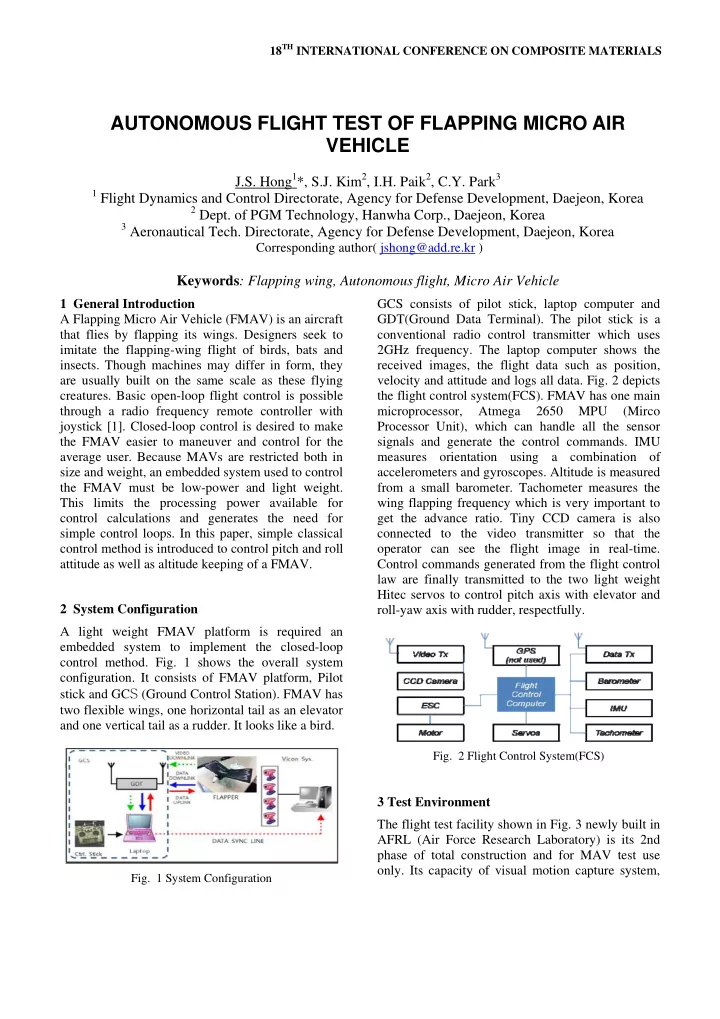
through a radio frequency remote controller with joystick [1]. Closed-loop control is desired to make the FMAV easier to maneuver and control for the average user. Because MAVs are restricted both in size and weight, an embedded system used to control the FMAV must be low-power and light weight. This limits the processing power available for control calculations and generates the need for simple control loops. In this paper, simple classical control method is introduced to control pitch and roll attitude as well as altitude keeping of a FMAV. 2 System Configuration A light weight FMAV platform is required an embedded system to implement the closed-loop control method. Fig. 1 shows the overall system

  • configuration. It consists of FMAV platform, Pilot

stick and GCS (Ground Control Station). FMAV has two flexible wings, one horizontal tail as an elevator and one vertical tail as a rudder. It looks like a bird.

  • Fig. 1 System Configuration

GCS consists of pilot stick, laptop computer and GDT(Ground Data Terminal). The pilot stick is a conventional radio control transmitter which uses 2GHz frequency. The laptop computer shows the received images, the flight data such as position, velocity and attitude and logs all data. Fig. 2 depicts the flight control system(FCS). FMAV has one main microprocessor, Atmega 2650 MPU (Mirco Processor Unit), which can handle all the sensor signals and generate the control commands. IMU measures orientation using a combination of accelerometers and gyroscopes. Altitude is measured from a small barometer. Tachometer measures the wing flapping frequency which is very important to get the advance ratio. Tiny CCD camera is also connected to the video transmitter so that the

  • perator can see the flight image in real-time.

Control commands generated from the flight control law are finally transmitted to the two light weight Hitec servos to control pitch axis with elevator and roll-yaw axis with rudder, respectfully.

  • Fig. 2 Flight Control System(FCS)

3 Test Environment The flight test facility shown in Fig. 3 newly built in AFRL (Air Force Research Laboratory) is its 2nd phase of total construction and for MAV test use

  • nly. Its capacity of visual motion capture system,

AUTONOMOUS FLIGHT TEST OF FLAPPING MICRO AIR VEHICLE

J.S. Hong1*, S.J. Kim2, I.H. Paik2, C.Y. Park3

1 Flight Dynamics and Control Directorate, Agency for Defense Development, Daejeon, Korea 2 Dept. of PGM Technology, Hanwha Corp., Daejeon, Korea 3 Aeronautical Tech. Directorate, Agency for Defense Development, Daejeon, Korea

Corresponding author( jshong@add.re.kr )

Keywords: Flapping wing, Autonomous flight, Micro Air Vehicle

slide-2
SLIDE 2

Vicon system, enables real-time vehicle flight data acquisition with the only addition of tiny and light retro-reflective markers to the vehicle.

  • Fig. 3. Test Facility in AFRL
  • Fig. 4 represents the result that vicon system

captures the markers on the FMAV. Vicon system can measure the flight data such as position, velocity and attitude with respect to the origin which is defined before flight. It enables us to compare the flight data which is acquired from the FCS and Vicon.

  • Fig. 4. Vicon system result

4 Controller Design and Implementation

4.1 Control Methods One way of simple closed-loop control is to use classical control which means PID(Proportional, Integral and Derivative) control for its simple and powerful capability. Most of the air vehicles such as fixed wing and rotary wing vehicles adopted this kind of control method. It motivates us to use same control law for the FMAV. Because it is difficult to get suitable mathematical models and aerodynamic models [2], we tried to find proper control gains by trial and errors. Before implementing the autonomous flight algorithm, we tried to do it step by step. We define the flight mode for this as in Table 1.

  • Table. 1. Flight Mode

Mode Description Manual Pilot stick command is directly transmitted to the elevator, rudder and throttle. Semi- Autonomous for Lateral Axis Elevator and throttle are controlled as Manual mode. Pilot stick for rudder is used as a roll attitude command. Roll is stabilized by PI control. Semi- Autonomous for Lateral and Pitch Axis Throttle is controlled as Manual

  • mode. Pilot sticks for rudder and

elevator are used as a roll and pitch attitude command respectfully. Roll and Pitch are stabilized by PI control. Autonomous Pilot stick is not used. Elevator, rudder and throttle are operated in fully autonomous to keep the certain altitude. 4.2 Manual Mode The first step is to fly by manual mode. As shown in

  • Fig. 5, all of the pilot stick commands are directly

transmitted to the servos and motor to control the elevator, rudder and throttle respectively. Manual mode is important step to verify the platform is flyable or not. In this test, a proficient pilot can fly it without difficulties.

3 Motor cmd 2 Servo Cmd (Elevator) 1 Servo Cmd (Rudder) INPUT THROTTLE STICK INPUT INPUT RUDDER STICK INPUT INPUT ELAVATOR STICK INPUT

  • Fig. 5. Manual Mode Control Loop

4.3 Semi-Autonomous Mode for Lateral Axis Second step is to design the control law for lateral

  • axis. Because the FMAV has only one rudder,

rudder input can cause roll and yaw coupled motion. In this paper, we focus on the roll motion only. Fig. 6 represents the control loop for the lateral axis. The pilot stick input for rudder is used as a roll command. Roll attitude (phi) is feedback to generate roll error and then the PI control loop stabilizes the lateral axis

  • motion. Generally, UAV, unmanned air vehicle,

with fixed wing uses rate feedback such as roll and

slide-3
SLIDE 3

3 AUTONOMOUS FLIGHT TEST OF FLAPPING MICRO AIR VEHICLE

pitch rate to enhance the damping ratio so as to increase the stability of the vehicle. FMAV can be said statically stable by numerous manual flight tests therefore rate feedback is not applied for this platform.

3 Motor cmd 2 Servo Cmd (Elevator) 1 Servo Cmd (Rudder) INPUT THROTTLE STICK INPUT Saturation INPUT RUDDER STICK INPUT

  • K-

PWM_Generator

  • K-

Kp_phi

  • K-

KpI_phi 1 s Integrator INPUT ELAVATOR STICK INPUT 1 phi(deg) Roll_Err Roll_Cmd Rudder Cmd

  • Fig. 6. Semi-autonomous mode for lateral axis
  • Fig. 7 shows the flight result. Roll attitude (GCU

Phi) follows the roll command (GCU Phi Cmd) for more than ten seconds. The negative roll command means the FMAV rotates counter-clock wise in the test room. The Vicon data (VICON Phi) shows almost same as the roll attitude which is calculated by the FCS. From this result, the navigation data from the FCS is reliable to feedback and roll motion is to track the command with rising time of around

  • ne second.

45 46 47 48 49 50 51 52 53 54 55

  • 50
  • 40
  • 30
  • 20
  • 10

10 20 time ROLL(deg) GCU Phi GCU Phi Cmd GCU Act Cmd VICON Phi

  • Fig. 7. Lateral axis response

4.4 Semi-Autonomous Mode for Lateral and Pitch Axis Next step is adding the closed-loop control for pitch

  • axis. Fig. 8 shows the control loop for stabilizing

both roll and pitch axis. Both loops are almost same in the structure by means of using PI control except that the nominal pitch angle is added with the elevator input for pitch control. It is required for the pilot to fly the FMAV near trim condition so as to reduce the work load of the pilot. The nominal pitch angle and controller gains such as proportional and integration gains are obtained after numerous semi- autonomous flights.

3 Motor Cmd 2 Servo Cmd (Elevator) 1 Servo Cmd (Rudder) INPUT THROTTLE STICK INPUT Saturation RudCmdLimit1 INPUT RUDDER STICK INPUT PitchCmdLimit

  • K-

PWM_Generator1

  • K-

PWM_Generator

  • C-

Nominal Pitch Angle

  • K-

Kp_theta

  • K-

Kp_phi

  • K-

KpI_phi

  • K-

Ki_theta 1 s Integrator1 1 s Integrator EleCmdLimit INPUT ELEVATOR STICK INPUT 2 theta(deg) 1 phi(deg) Roll_Err Roll_Cmd Rudder Cmd Theta_Err Pitch Cmd

  • Fig. 8. Semi-autonomous mode for lateral and pitch axis
  • Fig. 9 shows the result of this mode. The pitch

attitude (GCS pitch) follows pitch command (GCS pitch cmd) in 5deg during flight test. While turning flight for example from 15 to 17 seconds, the pitch cannot follow the command in desirable range. It is because large roll motion causes altitude drop and nonlinear characteristics. In this test, the FMAV flied clockwise for the first 17 second and counter- clockwise like “8” shaped trajectory.

5 10 15 20 25 30 35

  • 50
  • 40
  • 30
  • 20
  • 10

10 20 30 40 50 t[s] [deg] GCS pitch(deg) GCS pitch cmd(deg) GCS Ele Cmd+50 GCS roll(deg)

  • Fig. 9. Pitch axis response

4.5 Autonomous Flight Finally we

  • perate
  • ur

FMAV with fully autonomous mode with adding the closed-loop for

  • thrust. In this paper, thrust can control the altitude

with the help of pitch control loop. Fig. 10 shows the control-loop for fully autonomous flight. As same as the other loops, thrust can be managed by using PI control with proper altitude command. In this test, it

slide-4
SLIDE 4

is set up as 5m above the origin considering the test

  • facility. Elevator stick input is available, just for the

emergency, to prevent the vehicle from crashing on the wall. In this test however, the pilot tried not to use the elevator stick input as possible.

Altitude Command can be changed by GCU Elevator Stick Input is augmented for abrupt turning 3 Cmd_Motor 2 Servo Cmd (Elevator) 1 Servo Cmd (Rudder) Saturation RudCmdLimit1 INPUT RUDDER STICK INPUT RPMCmdLimit PitchCmdLimit

  • K-

PWM_Generator1

  • K-

PWM_Generator Nominal_Pitch_Angle Nominal Pitch Angle

  • K-

Kp_theta

  • K-

Kp_phi

  • K-

Kp_RPM

  • K-

Kp_AltforTheta

  • K-

Kp_Alt

  • K-

KpI_phi

  • K-

Ki_theta

  • K-

Ki_RPM

  • K-

Ki_Alt 1 s Integrator3 1 s Integrator2 1 s Integrator1 1 s Integrator EleCmdLimit INPUT ELEVATOR STICK INPUT 5 Altitude Cmd(m) 4 Altitude(m) 3 Throttle(RPM) 2 theta(deg) 1 phi(deg) Roll_Err Roll_Cmd Rudder Cmd Theta_Err Alt_Err Throttle Cmd Pitch Cmd

  • Fig. 10. Autonomous mode
  • Fig. 11 depicts the result of the fully autonomous
  • flight. The FMAV keep altitude within one meter for

ten seconds almost without pilot input. Pilot used very small amount of elevator stick input for less than 4 second. From this result, it is concluded that the FMAV can fly with tiny flight control computer. Even though the controller design did not start from the aerodynamic models as the designer do for the conventional aircraft, it is possible to implement fully autonomous flight with classical control method.

70 71 72 73 74 75 76 77 78 79 80 5 10 15 20 25 30 t[s] [deg] GCS pitch(deg) GCS RPM Alt + 10(m) GCS Roll(deg) + 50 Alt Cmd + 10(m) GCS pitch cmd(deg)

  • Fig. 11. Autonomous flight result

5 Conclusion In this paper, autonomous flight test is described. Because the light weight FMAV platform is required an embedded system to implement the closed-loop control method, tiny flight control computer is

  • introduced. It can send or receive the flight data

through the data modem and pilot can transmit the control stick inputs. It is difficult to model the aerodynamic characteristics of flapping wing so we developed autonomous flight control law step by

  • step. The platform is verified by manual flight. Then

classical control method is applied to attitude control. It is successful to maintain its attitude command. The classical control method is introduced to the thrust control as well. As a result, the altitude can be kept within desirable range by the fully autonomous

  • flight. Even though the controller design did not start

from the aerodynamic models as the designer do for the conventional aircraft, it is possible to implement fully autonomous flight with classical control method. 6 Acknoledgements The authors would like to thank the Air Force Research Laboratory in United States for their support in this research. References

[1] Katherine Sarah Shigeoka, “Velocity and Altitude Control of an Ornithopter Micro Air Vehicle”, Master Thesis, 2007. [2] Jared Grauer, Evan Ulich, James Hubbard Jr., Darryll Pines, and J. Sean Humbert, “System Identification

  • f an Ornithopter Aerodynamics Model”, AIAA

Atmospheric Flight Mechanics Conference, 2010. [3] Jared Grauer, James Hubbard Jr., “Modeling of

  • rnithopter flight dynamics for state estimation and

control”, American Control Conference, 2010. [4] Jared Grauer and james Hubbard Jr., “Multibody Model of an Ornithopter”, Journal of Guidance, Control, and Dynamics, Vol. 32, No. 5, 209.