
SLIDE 1
1 IMAPS/ACerS 11th CICMT, Dresden, 20-23.4.2015
Thomas Maeder, Caroline Jacq and Peter Ryser
École Polytechnique Fédérale de Lausanne (EPFL), Switzerland
Assessment of TFRs for piezoresistive sensors
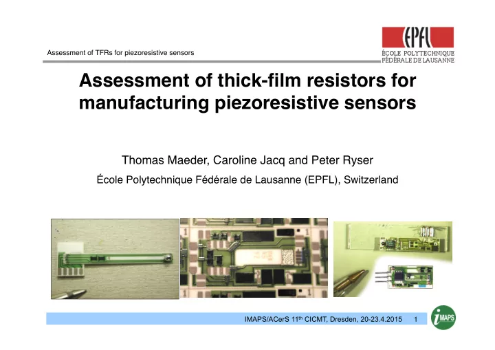
Assessment of thick-film resistors for manufacturing piezoresistive - - PowerPoint PPT Presentation
Assessment of TFRs for piezoresistive sensors Assessment of thick-film resistors for manufacturing piezoresistive sensors Thomas Maeder, Caroline Jacq and Peter Ryser cole Polytechnique Fdrale de Lausanne (EPFL), Switzerland IMAPS/ACerS 11
1 IMAPS/ACerS 11th CICMT, Dresden, 20-23.4.2015
Assessment of TFRs for piezoresistive sensors
2 IMAPS/ACerS 11th CICMT, Dresden, 20-23.4.2015
Outline
3 IMAPS/ACerS 11th CICMT, Dresden, 20-23.4.2015
Outline
4 IMAPS/ACerS 11th CICMT, Dresden, 20-23.4.2015
n Typical elements
n Sensing bridge n Offset trim n TCO trim n Differential amplifier
n Typical values (±)
n Offset ~30 mV/V n Response ~3 mV/V n TCO ~1 µV/V/K
n For 0.1% F.S.:
n Offset reduction ~10'000× n Stability (bridge) ~10 ppm
1 - Introduction
5 IMAPS/ACerS 11th CICMT, Dresden, 20-23.4.2015
n Modern digital chips
n Input stage usually PGA (programmable-gain amplifier) n Gain limited by signal n In raw state, offset dominates signal, >> response
n For optimal use, reduce offset to < response
n With typical raw offset ~30 mV/V, max. gain ~30× n With typical response ~3 mV/V, typ. gain required ~200× n Reduce offset typically by ~10…30×
n Trimming of TCO usually not necessary with chips
n Typically, temperature error <10% of piezoresistive response n Can be done digitally n Laser trim: large-scale production; better temperature sensing
1 - Introduction
6 IMAPS/ACerS 11th CICMT, Dresden, 20-23.4.2015
1 - Introduction
n All-active bridge n Coarse offset trim on cell n Direct TCO trim
n Need good amplifier – usually not
n Issue: trim on dielectric n Coarse offset trim off-cell n Indirect TCO trim
n PTC resistor on cell n Normal resistor in parallel
7 IMAPS/ACerS 11th CICMT, Dresden, 20-23.4.2015
1 - Introduction
n All-active bridge n Discrete offset trim (stable, active, ~no TCO change) n Coarse classical trim (more precise) n No TCO trim (on base, with fine trim) Top Bottom
8 IMAPS/ACerS 11th CICMT, Dresden, 20-23.4.2015
1 - Introduction
n All-active bridge n Discrete offset trim cuts only
n All other trims on separate
9 IMAPS/ACerS 11th CICMT, Dresden, 20-23.4.2015
1 - Introduction
n Normally passive & active part n High resistor values often problematic n Harsh post-processing (breaking, soldering, ultrasound, …) Top
10 IMAPS/ACerS 11th CICMT, Dresden, 20-23.4.2015
1 - Introduction
n Resistor interactions
n Substrate (Al2O3, dielectric, LTCC…) n Terminations n Overglaze n TCO ≠ TCR; TCO determined by TCR tracking
n Trimming
n Discrete (stable) or classical (precise) n Trimming resistor used (coarse: use same as bridge) n Terminations (material near terminations ≠ away) n Parameters & resistor material
n Post-processing
11 IMAPS/ACerS 11th CICMT, Dresden, 20-23.4.2015
Outline
12 IMAPS/ACerS 11th CICMT, Dresden, 20-23.4.2015
1 - Introduction
n (Substrate = alumina) n Termination material n Resistor material & length n Overglaze material
13 IMAPS/ACerS 11th CICMT, Dresden, 20-23.4.2015
1 - Introduction
n Resistor under…overfired
n See whether this changes its interactions with overglaze
n Overglaze under…overfired
n Extent of effect on resistor
14 IMAPS/ACerS 11th CICMT, Dresden, 20-23.4.2015
1 - Introduction
n Newer resistor compositions (DP 2041 / R314P) better n Thin Au (D) terminations = lowest spread
n Low geometric disturbance of screen printing n Low diffusion with terminations
15 IMAPS/ACerS 11th CICMT, Dresden, 20-23.4.2015
1 - Introduction
n Less difference seen in 100 Ω compositions n Not dominant – used for fine trimming
16 IMAPS/ACerS 11th CICMT, Dresden, 20-23.4.2015
1 - Introduction
n Process dependence of value & TCR different n Strong length effects on TCR -> TCO for short resistors
17 IMAPS/ACerS 11th CICMT, Dresden, 20-23.4.2015
Outline
18 IMAPS/ACerS 11th CICMT, Dresden, 20-23.4.2015
3 –Overglazing, trimming, …
n Overglazing above nominal temperature – : strong drift n Length dependence on ∆TCR: leads to TCO
19 IMAPS/ACerS 11th CICMT, Dresden, 20-23.4.2015
n Behaviour mostly normal: slight value increase n Decrease of value for 100 kΩ composition!
3 – Overglazing, trimming, …
20 IMAPS/ACerS 11th CICMT, Dresden, 20-23.4.2015
3 – Overglazing, trimming, …
n Au initially ~2× better
n After trimming n Trim + ultrasound
n Advantage lost upon
n Trim-overglaze
n Temperature not so
n Better: refire
2 4 6 8 40% AgPd 45% AgPd 50% AgPd 40% Au 45% Au 50% Au ca.
mV/V
2 4 6 8
21 IMAPS/ACerS 11th CICMT, Dresden, 20-23.4.2015
Outline
22 IMAPS/ACerS 11th CICMT, Dresden, 20-23.4.2015
n Thick-film piezoresistive sensors & laser trimming
n Relatively low signal + harsh environments: difficult n High process temperatures -> materials interactions critical n Few alternatives to laser trimming (voltage?) for large series (cost) n Best stability: start with discrete coarse trims n Parameter development can be tedious n Must ensure access of beam to resistor (not always practical!)
n Software offset trimming
n Radj = same paste as bridge,
n Little to no effect on TCO
4 - Conclusions & outlook
23 IMAPS/ACerS 11th CICMT, Dresden, 20-23.4.2015
4 - Conclusions & outlook
24 IMAPS/ACerS 11th CICMT, Dresden, 20-23.4.2015
Measurement of gauge factor
n Alumina cantilever n Effective signal ~independent of loading errors