
SLIDE 1
ALMA Future Science Development Program Workshop (24-25 Aug 2016)
1
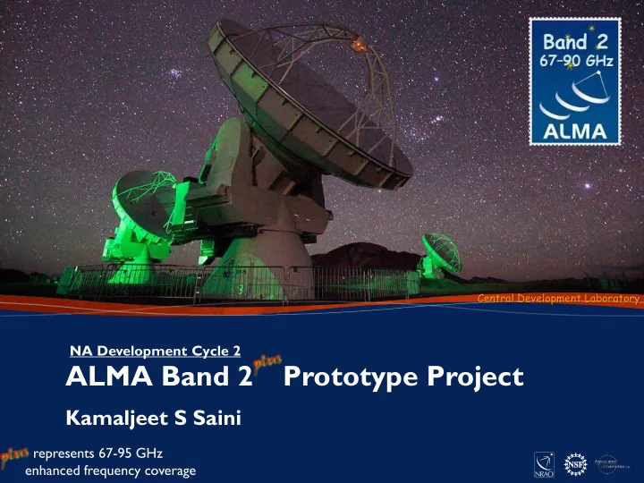
ALMA Band 2 Prototype Project
Kamaljeet S Saini
NA Development Cycle 2
Central Development Laboratory
represents 67-95 GHz enhanced frequency coverage
ALMA Band 2 Prototype Project Kamaljeet S Saini represents 67-95 - - PowerPoint PPT Presentation
Central Development Laboratory NA Development Cycle 2 ALMA Band 2 Prototype Project Kamaljeet S Saini represents 67-95 GHz 1 enhanced frequency coverage ALMA Future Science Development Program Workshop (24-25 Aug 2016) ALMA Band 2 Prototype
ALMA Future Science Development Program Workshop (24-25 Aug 2016)
1
NA Development Cycle 2
Central Development Laboratory
represents 67-95 GHz enhanced frequency coverage
ALMA Future Science Development Program Workshop (24-25 Aug 2016)
2
ALMA Future Science Development Program Workshop (24-25 Aug 2016)
3
13CO, 13C2H, H13CO+, HC18O, H13CN, HC15N, H2CO, HCNH+
ALMA Future Science Development Program Workshop (24-25 Aug 2016)
4
Band 2+
ALMA Future Science Development Program Workshop (24-25 Aug 2016)
5
ALMA Future Science Development Program Workshop (24-25 Aug 2016)
6
ALMA Future Science Development Program Workshop (24-25 Aug 2016)
7
ALMA Future Science Development Program Workshop (24-25 Aug 2016)
8
110 K & 15 K IR Filters Ortho Mode Transducer Window (Lens) Bias Filter Card Cold Cartridge Assembly 40.02.02 Warm Cartridge Assembly 40.10.02 110 K Stage 15 K Stage
HFET Amplifier HFET Amplifier
WR-12 Waveguide
RF: 67 – 90 GHz LO: 73.6 – 88.3 GHz Amplifier Bias
IF Outputs 4 – 12 GHz DC Power Optical Reference Signal First LO Offset Reference M&C Lines
Pol-0 Pol-1
ICD1 ICD2 ICD3 ICD4
ALMA Band-2 Receiver 67 – 90 GHz Top Level Block Diagram Revised 18 Mar 2016
ICD1 ICD2 ICD3 ICD4 ICD5
INTERFACES
Cold Cartridge Assembly to ALMA Cryostat Cold Cartridge Assembly to Warm Cartridge Assembly Cold Cartridge to Bias Module FE LO to BE Photonics LO Cold Cartridge Assembly to IF Switch Subsystem
ICD5 ICD6 ICD6
Warm Cartridge Assembly to Harness Plate
I/O Signals to/from the Receiver (Harness Plate)
Frequency Tripler AMC PA X3 Photo Mixer Phase Locked Loop 12.27 – 14.72 GHz
Cartridge Bias Module 40.04.02
LO M&C Power Amplifier Drain Bias PA 2SB Processor 2 Repeats (for Pol-0 & Pol-1) Pol-0 LO for Pol-1 90o 90o MCDPLL Warm IF Amplifiers Pol-1
Pol-0 Pol-1
YTO USB IF LSB IF Horn X2 Frequency Doubler
ALMA Future Science Development Program Workshop (24-25 Aug 2016)
9
Feedhorn Ortho-mode transducer Low Noise Amplifier(s) 15 K Stage 110 K Stage 300 K Baseplate Thermal links to 15 K stage Thermal anchors
ALMA Future Science Development Program Workshop (24-25 Aug 2016)
10
IF amplifiers 90º IF hybrid(s) RF input from cold cartridge YIG Tuned Oscillator Active Multiplier Chain and Power amplifier Heatsink
ALMA Future Science Development Program Workshop (24-25 Aug 2016)
11
Test Cryostat Front-End Electronics Chassis Tilt Table Environmental Chamber HVAC NSI Beam Scanner FETMS Equipment Racks Front-End Support Structure (FESS)
ALMA Future Science Development Program Workshop (24-25 Aug 2016)
12
Band 2 Receiver stage Gain Cumulative Gain to preceding stage Noise Figure Noise Temperature Tequivalent
(for MIC based)
Lens/Window (room temperature)
0.0 dB 0.1 dB 8.9 K 8.9 K IR Filters (15 K and 80 K)
0.1 dB 1.4 K 1.5 K Feedhorn (15 K)
0.1 dB 0.3 K 0.4 K OMT
0.1 dB 0.3 K 0.4 K E-Band Amplifier (15 K) 35.0 dB
36.5 K 40.6 K Waveguides, feed-thru and BPF
34.5 dB 4.0 dB 453.6 K 0.2 K E-Band Amplifier (room temperature) 14.0 dB 30.5 dB 3.5 dB 371.6 K 0.3 K 2 SB Downconverter
44.5 dB 12.0 dB 4454.7 K 0.2 K Warm IF Amplifier 30.0 dB 32.5 dB 2.0 dB 175.5 K 0.1 K Total 62.5 dB 52.4 K
(MIC)
Tequivalent
(for MMIC)
8.9 K 1.5 K 0.4 K 0.4 K 29.2 K 0.2 K 0.3 K 0.2 K 0.1 K 41.1 K
ALMA Future Science Development Program Workshop (24-25 Aug 2016)
13
110 K Stage
Bands 1 - 2 Band 3 Bands 4 - 8 Bands 9 - 10 Sum Passive heat load 450 mW 350 mW
700 mW
600 mW 5950 mW Active heat load 150 mW 50 mW
150 mW
250 mW 550 mW Total heat load 600 mW 400 mW
850 mW
850 mW 6500 mW
15 K Stage
Bands 1 - 2 Band 3 Bands 4 - 5, 8 - 10 Band 6 Band 7 Sum Passive heat load 95 mW 95 mW 95 mW 75 mW 115 mW 950 mW Active heat load 90 mW 20 mW 67 mW 67 mW 15 mW 200 mW Total heat load 185 mW 115 mW 162 mW 162 mW 130 mW 1150 mW
ALMA Future Science Development Program Workshop (24-25 Aug 2016)
14
ALMA Future Science Development Program Workshop (24-25 Aug 2016)
15
ALMA Future Science Development Program Workshop (24-25 Aug 2016)
16
Lens # Illumination taper at 3.6° (dB) 67 GHz 78 GHz 90 GHz 2
3
4 (Fresnel, 1-zone)
78 GHz 78 GHz
ALMA Future Science Development Program Workshop (24-25 Aug 2016)
17
ALMA Future Science Development Program Workshop (24-25 Aug 2016)
18
Pol-0 Pol-1
ALMA Future Science Development Program Workshop (24-25 Aug 2016)
19
Location of center of the lens can be measured from an arbitrary (fixed) fiduciary mark on the cryostat using a beam-scanner mounted red laser → Can adjust lens position by a given (delta) amount from existing position, to get desired beam pointing.
Band 2 Lens / Window
ALMA Future Science Development Program Workshop (24-25 Aug 2016)
20
ALMA Future Science Development Program Workshop (24-25 Aug 2016)
21
ALMA Future Science Development Program Workshop (24-25 Aug 2016)
22
ALMA Future Science Development Program Workshop (24-25 Aug 2016)
23
ALMA Future Science Development Program Workshop (24-25 Aug 2016)
24
ALMA Future Science Development Program Workshop (24-25 Aug 2016)
25
ALMA Future Science Development Program Workshop (24-25 Aug 2016)
26
ALMA Future Science Development Program Workshop (24-25 Aug 2016)
27
52.4 K
ALMA Future Science Development Program Workshop (24-25 Aug 2016)
28
ALMA Future Science Development Program Workshop (24-25 Aug 2016)
29
ALMA Future Science Development Program Workshop (24-25 Aug 2016)
30
ALMA Future Science Development Program Workshop (24-25 Aug 2016)
31
ALMA Future Science Development Program Workshop (24-25 Aug 2016)
32
ALMA Future Science Development Program Workshop (24-25 Aug 2016)
33
The National Radio Astronomy Observatory is a facility of the National Science Foundation