
SLIDE 1
1 General Introduction In this study, the behavior analysis of human right arm under impact condition was performed by creating the human model of Korean both the impact force and the applied load of the specific joint through a simulation of occurred condition with hammering impact was obtained right arm was modeled by muscle-skeleton elements to obtain the behavior of right arm of human under impact condition, where physical and geometrical properties of human body such as Young's modulus, shear modulus, cross sectional area, length, density, moment of inertia and position were defined. Based
- n the numerical model of the right arm, the impact
response of the right arm was obtained. By the comparison with the experimental results, the model
- f the right arm was verified.
The behavior of human right arm under impact condition is affected by the characteristic of the human muscle-skeleton model. The behavior of human right arm affects the further research activity in biomechanics and survivability study. by hammering is transferred to the segment of the human right arm. The finite element model and the analysis method were needed to analyze and compare with experimental results. 2 Characteristics of Analytical Model 2.1 Biomechanical Model of Human Right Arm The biomechanical model is based on the element method to the different aspects of biomechanical human body movement, which is kinematical and dynamical analysis of spatial
A STUDY ON THE BEHAV ARM UNDER IMPACT CON
J.
1 Ground Weapon System R&D, Agency
*
Keywords
18TH INTERNATIONAL CONFERENCE ON COMPOSITE
behavior analysis of human right was performed by young men and both the impact force and the applied load of the joint through a simulation of occurred was obtained. The skeleton elements avior of right arm of human under physical and geometrical properties of human body such as Young's modulus, shear modulus, cross sectional area, length, density, moment of inertia and position were defined. Based
- del of the right arm, the impact
response of the right arm was obtained. By the comparison with the experimental results, the model human right arm under impact condition is affected by the characteristic of the he behavior of the further research activity
- study. The impact
to the segment of the human right arm. The finite element model and the to analyze and Model Biomechanical Model of Human Right Arm is based on the finite to the different aspects of human body movement, which is kinematical and dynamical analysis of spatial movements of human body human muscles are determined analysis method. [1-4] Table 1. Physical condition of Model Stature (cm) Analytical 174 Experimental 174 Size Korea [5] 174 In this study, physical condition of 50 percentile Korean young m report of Size Korea 2005 human modeling for operat and shooting the small arms,
- f forearm and upper arm is
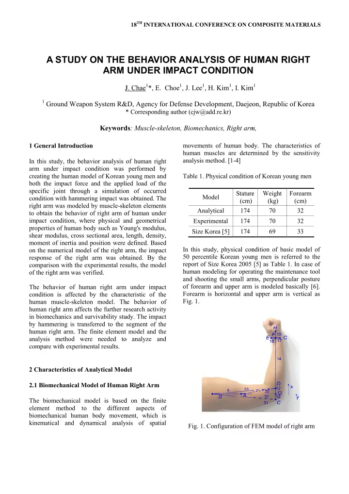
Forearm is horizontal and upper arm is vertical
- Fig. 1.
- Fig. 1. Configuration of FEM model of right arm
A STUDY ON THE BEHAVIOR ANALYSIS OF HUMAN RIGHT ARM UNDER IMPACT CONDITION
- J. Chae1*, E. Choe1, J. Lee1, H. Kim1, I. Kim
Ground Weapon System R&D, Agency for Defense Development, Daejeon, Republic
* Corresponding author (cjw@add.re.kr)
Keywords: Muscle-skeleton, Biomechanics, Right arm
COMPOSITE MATERIALS
movements of human body. The characteristics of human muscles are determined by the sensitivity Physical condition of Korean young men Stature Weight (kg) Forearm (cm) 70 32 70 32 69 33 condition of basic model of young men is referred to the [5] as Table 1. In case of human modeling for operating the maintenance tool and shooting the small arms, perpendicular posture
- f forearm and upper arm is modeled basically [6].