a study of compressed co 2 energy storage system for
play

A Study of Compressed CO 2 Energy Storage System for Nuclear Power - PDF document

Transactions of the Korean Nuclear Society Virtual Spring Meeting July 9-10, 2020 A Study of Compressed CO 2 Energy Storage System for Nuclear Power Plants Application Soyoung Lee a , Yongju Jeong a , Jeong Ik Lee a* a Department of Nuclear and


  1. Transactions of the Korean Nuclear Society Virtual Spring Meeting July 9-10, 2020 A Study of Compressed CO 2 Energy Storage System for Nuclear Power Plants Application Soyoung Lee a , Yongju Jeong a , Jeong Ik Lee a* a Department of Nuclear and Quantum Engineering, KAIST, Daejeon, South Korea * Corresponding author: jeongiklee@kaist.ac.kr 1. Introduction According to the 8th Basic Power Supply and Demand plan, the share of renewable energy will increase. As a result, the load that thermal and nuclear power plants have to deal with during the daytime are reduced. When this phenomenon becomes severe, the exact demand for base energy cannot be predicted, and the cost of power generation increases. Therefore, it is necessary to study the Energy Storage System (ESS) that can store coal and nuclear energies, which are responsible for the base load. Among ESSs, Compressed Air Energy Storage (CAES) is technically feasible. If carbon dioxide, which has large density and high site selection freedom, is used instead of air, a more effective mass storage device can be realized. This is called Compressed CO 2 Energy Storage (CCES) system. In the case of nuclear power plants, some of the energy generated from the steam turbine of 
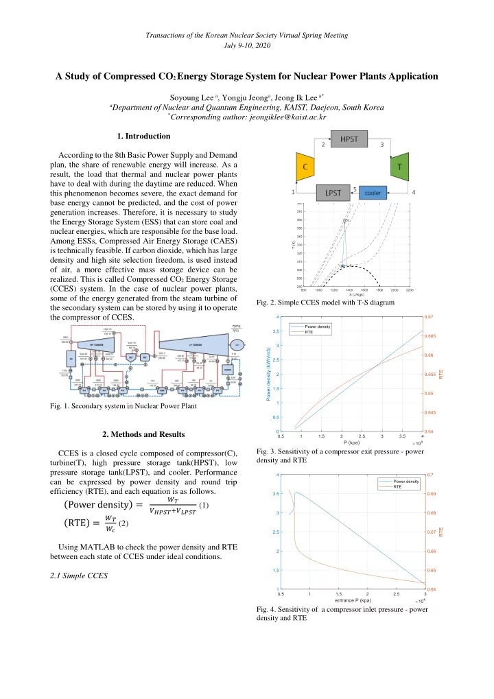
Fig. 2. Simple CCES model with T-S diagram the secondary system can be stored by using it to operate the compressor of CCES. Fig. 1. Secondary system in Nuclear Power Plant 2. Methods and Results Fig. 3. Sensitivity of a compressor exit pressure - power CCES is a closed cycle composed of compressor(C), density and RTE turbine(T), high pressure storage tank(HPST), low pressure storage tank(LPST), and cooler. Performance can be expressed by power density and round trip efficiency (RTE), and each equation is as follows. 𝑋 π‘ˆ (Power density) = π‘Š πΌπ‘„π‘‡π‘ˆ +π‘Š π‘€π‘„π‘‡π‘ˆ (1) 𝑋 π‘ˆ 𝑑 (2) (RTE) = 𝑋 Using MATLAB to check the power density and RTE between each state of CCES under ideal conditions. 2.1 Simple CCES Fig. 4. Sensitivity of a compressor inlet pressure - power density and RTE

  2. Transactions of the Korean Nuclear Society Virtual Spring Meeting July 9-10, 2020 2.2 Application with Thermal Energy Stroage(TES) in CCES Fig. 5. Sensitivity of a compressor efficiency - power density and RTE Fig. 7. Application with TES in CCES with T-S diagram Fig. 6. Sensitivity of a turbine efficiency - power density and RTE From Fig.4, at the temperature of compressor inlet is 304.1282K and pressure is 7694kPa, power density reaches maximum. Also higher outlet pressure of the compressor and higher efficiency of the turbine lead to higher, power density and RTE. However, at higher compressor efficiency, it has lower power density. Because, as the compressor efficiency increases, the temperature of CO 2 at the compressor outlet decreases, which results in smaller enthalpy difference. Fig. 8. Comparison of Power density between simple CCES and applied TES Table I: simple CCES state Temperature (K) Pressure (kpa) 1 304.1282 7694 2 356.6284 40000 3 356.6284 40000 4 304.9961 7694 5 304.1282 7694 The power density and RTE of simple CCES obtained through the above states are 3.5262 kWh/ 𝑛 3 and 0.6701, respectively. Fig. 9. Temperature change of HPST according to compressor outlet pressure

  3. Transactions of the Korean Nuclear Society Virtual Spring Meeting July 9-10, 2020 To apply the TES at HPST of CCES. TES serves to store thermal energy. However, there is no significant difference of the power density between simple CCES and TES applied model. The reason is that the temperature difference between the inlet and the outlet of the compressor is not large. Therefore, when using TES, the effect of reducing the volume by reducing storage temperature is not too great. Table β…‘ : state of applied TES with CCES Temperature (K) Pressure (kpa) 1 304.1282 7694 2 356.6284 40000 3 304.1282 40000 4 304.1282 40000 Fig. 11. Sensitivity of compressor inlet temperature - power 5 356.6284 40000 density and RTE 6 304.9961 7694 7 304.1282 7694 The power density and RTE of applied TES model obtained through the above states are 3.8263 kWh/ 𝑛 3 and 0.6701, respectively. 2.2 Transcritical CCES Fig. 12. Sensitivity of compressor outlet pressure - power density and RTE Fig. 13. Sensitivity saturation temperature - power density and RTE Fig. 10. Transcritical CCES with T-S diagram A heat exchanger is on the low temperature section, It has higher power density and RTE, when the and carbon dioxide is stored as liquid phase in the LPST. pressure of compressor outlet is higher and, carbon This is called Transcritical CCES as the working fluid is dioxide in the heat exchanger at the lower temperature partially at liquid phase in the cycle. section is saturated. From Fig.12, it has better performance when compressor outlet pressure is higher. This is because it has larger expansion work when compressor outlet pressure is higher. The volume of carbon dioxide stored in the LPST decreases as the CO 2

  4. Transactions of the Korean Nuclear Society Virtual Spring Meeting July 9-10, 2020 becomes saturated condition at lower temperature, thereby increasing the power density. This is shown in Fig. 13. Table β…’ : state of transcritical CCES Temperature (K) Pressure (kpa) 1 283.15 45022 2 474.8596 40000 3 338.1193 7214 4 311.7590 7214 5 303.15 7214 6 303.15 7214 7 283.15 45022 The power density and RTE of transcritical CCES are 7.0574 kWh/ 𝑛 3 and 0.6088, respectively. 3. Conclusions In this study, the basic concept and characteristics of CCES (Compressed CO 2 energy storage) were discussed. In addition, various applications such as applying hot TES or storing CO2 as liquid using heat exchangers were also discussed. As a result, it was confirmed that the performance can be improved by increasing the compressor outlet pressure and storing CO 2 in the LPST in the form of liquid state at lower temperature. For future study, the upper pressure limit of HPST and the method to lower the saturation temperature in the heat exchanger should be developed. It is also expected that CCES could be applied to nuclear power plants as a large-capacity energy storage system. REFERENCES [1] Y. Zhang, K. Yang, H. Hong, X. Zhong, J. Xu, Thermodynamic Analysis of a Novel Energy System with Carbon Dioxide as Working Fluid, Renewable Energy 99, pp.682-697,2016. [2] M. Budt, D. Wolf, R. Span, J. Yan, A Review on Compressed Air Energy Storage Basic Principles, Pastmilestones and Developments, Applied Energy 170, pp.250-268, 2016. [3] H. Liu, Q. He, A. Borgia, L. Pan, Thermodynamic Analysis of a Compressed Carbon Dioxide Energy Storage Using Two Saline Aquifers, Energy Conversion and Management 127, pp.149-159, 2016.

Download Presentation
Download Policy: The content available on the website is offered to you 'AS IS' for your personal information and use only. It cannot be commercialized, licensed, or distributed on other websites without prior consent from the author. To download a presentation, simply click this link. If you encounter any difficulties during the download process, it's possible that the publisher has removed the file from their server.

Recommend


More recommend