a rf gun cooling system
play

A RF-Gun Cooling System Presented by: Danielle Hannah Supervised - PowerPoint PPT Presentation

A RF-Gun Cooling System Presented by: Danielle Hannah Supervised by: Maurice Ball Jamie Santucci 1 Danielle N. Hannah Born and raised in Marietta, Georgia Spelman College/North Carolina A&T Dual Degree Engineering


  1. AØ RF-Gun Cooling System
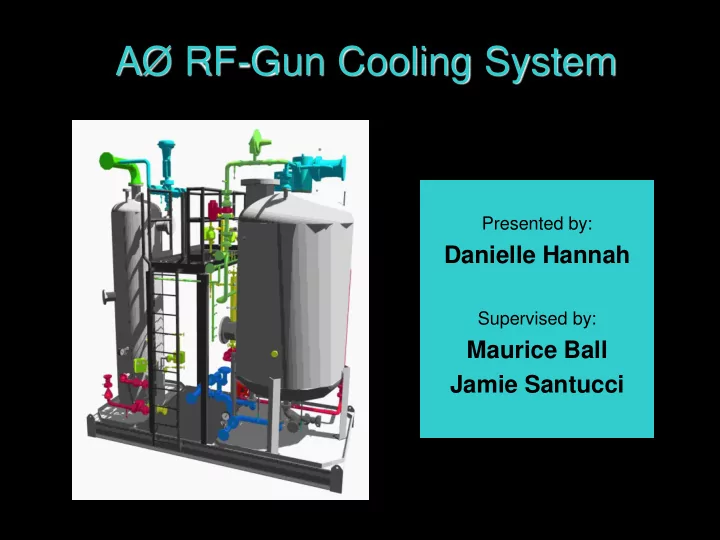
 Presented by: Danielle Hannah Supervised by: Maurice Ball Jamie Santucci 1

  2. Danielle N. Hannah • Born and raised in Marietta, Georgia • Spelman College/North Carolina A&T – Dual Degree Engineering Program (DDEP) • B.A. Mathematics and B.A. Architectural Engineering – Rising Junior 2 • Summer Internships in Science and Technology (SIST)

  3. AØ Experiment • The AØ Photoinjector (AØPI) facility is a small research and development program section within the Accelerator Division (AD). • An essential component of the overall AØPI is a Radio Frequency Electron Gun (RF-gun). • The RF-gun is located in the south cave of the AØ building. • This gun consists of cavities that are used to accelerate a beam of electrons. 3

  4. Project Background • The RF-gun emits heat. • This poses a problem to the well-being of the machine and the physicists.  Engineers of the Mechanical Support Department created a low- conductivity water (LCW) skid cooling system to keep the RF-gun at a consistent temperature. • Within the next 5 years, a new RF-gun will be installed in the AØ north cave. • The new RF-gun will use the same cooling system as the current gun.  But before the installation occurs it must be assured that the current cooling system for the AØ PI RF-gun is up to par. 4

  5. Project Description • This presents how the AØ PI RF-gun skid system was characterized, improved, and documented over the course of a summer. • In order to obtain these goals the following steps had to be executed: – Outlined spreadsheet acting as a project timeline, – Development of a detailed system schematic, – Refinement of the system’s appearance, – Completed fluid analysis throughout system. 5

  6. System Schematic 6

  7. Draft #1 7

  8. Final Draft 8

  9. Draft #1 9

  10. Final Draft 10

  11. System Updates 11

  12. Re-Labeling 12

  13. Original Labels 13

  14. Original Labels 14

  15. New Labels 15

  16. New Labels 16

  17. 17

  18. Flow Rate Measurements 18

  19. Section 1: Q = 30.0 gpm 2 3 1 Section 2: Q = 24.4 gpm Q = 29.9 gpm Section 3: Q = 5.5 gpm 19

  20. Flow Fluid Analysis 20

  21. Bernoulli’s Principle • The most useful single equation in fluid mechanics. • States that for an inviscid flow, an increase in the speed of the fluid occurs simultaneously with a decrease in pressure. 2 2 144 p v 144 p v 1 1 2 2 Equation 1 z z h 1 2 L 2 g 2 g 1 2 elev . head press . head vel . head elev . head press . head vel . head 1 1 1 2 2 2 21

  22. Fluid Flow Analysis • Bernoulli’s Equation (Equation 1) can be expressed as: 2 2 v v 2 1 P P h Equation 2 2 1 L 144 2 g in order to calculate the change in pressure from P 1 to P 2 . 2 0 . 00259 KQ h L Equation 3 4 d fL K Equation 4 [h L =head loss (ft), Re= Reynold’s D number, K=resistance coefficient, 50 . 6 Q R e Equation 5 Z=elevation (ft), P=pressure (psi), d ρ =weight density (lb/ft 3) , v=velocity (ft/s), μ =absolute viscosity (cP), 64 f Equation 6 d=diameter (in), D=diameter (ft), R e f=friction factor, Q=rate of flow (gpm), L=pipe length (ft), g=acceleration of gravity (ft/s 2 )] • In efforts to minimize errors, the entire system was separated into 13 sections (A-M). 22

  23. Sections A-G, L-M 23

  24. Sections G-L 24

  25. Pressure Drop Calculation: Section A Given: Measured: • • f T = 0.019 d = 0.17225 ft • • μ = 1.7 cP Z 2 = 9.833 ft • • ρ = 62.42 lb/ft 3 Z 1 = 0 ft • L = 69.5 ft • v = 2.87 ft/s • Q = 30 gpm Assumptions: • All fittings are standard 45 or 90 elbows. Calculations: • 50 . 6 30 gal 62 . 42 lb 1 94753 . 6 R e = = 2.7 x 10 4 3 2 . 067 in min ft 1 . 7 cP 3 . 5139 • f = 0.026 0 . 026 69 . 5 ft 12 in 21 . 684 • = 10.490 K = 2 . 067 in ft 2 . 067 = 0.608  2 16 0 . 019 45 = 16f T = 6.84  12 30 0 . 019 90 = 30f T = 17.95 • K TOTAL = 0.608 + 6.84 + 10.49 2 17 . 95 30 gal 41 . 84 • = 2.292 ft h L = 0 . 00259 4 2 . 067 in min 18 . 254 25 2 62 . 42 lb ft = 5.256 psi 9 . 833 ft 0 ft 2 . 292 ft • Δ P = 2 3 144 in ft

  26. Total System Pressure Drop AØ RF-Gun Skid System gauge readings Pressure Gauge psi Temperature Gauge F • Section A = 5.256 psi P-01 33 T-01 53 • Section B = 1.664 psi P-02 13 T-02 36 • P-03 7.5 T-03 51 Section C = 0.893 psi P-04 62.5 T-04 50.5 • Section D = 2.484 psi P-05 9 T-05 65 • P-06 7 T-06 45 Section E = 1.398 psi P-07 140 T-07 60 • Section F = 1.061 psi P-08 137 T-08 58 • Section G = 5.174 psi P-09 19 T-09 44 P-10 9.5 T-10 82 • Section H = 1.423 psi P-11 5 • Section I = 1.134 psi P-12 141 P-13 135 • Section J = 4.213 psi P-14 10 • Section K = 4.444 psi P-15 54 • P-16 10 Section L = 5.561 psi P-17 22 • Section M = 3.909 psi P-18 25 P-19 22 Section A + B + C +…K + L + M = Entire Gauge Pressure Drop = 26 38.614 psi or 89.198 ft 134 psi or 309.54 ft

  27. Project Timeline 27

  28. Project Manager 28

  29. Summary A system schematic was perfected The entire system’s temperature and pressure gauges were re-labeled The drop in pressure (calculated) throughout the system was compared with the drop in pressure (readings) to conclude that the gauge readings were inaccurate.  Thus, the current cooling system is not up to par. 29

  30. Future Goals Develop a procedure to switch RF-gun cooling back and forth from North Cave to South Cave Develop instrumentation for the system to data log on ACNET, a control system that accelerators use. 30

  31. Acknowledgments • Maurice Ball, AD, Engineering, Mechanical Support Dept. • Jamie Santucci, AD, Photoinjector • Elmie Peoples-Evans, APC High Intensity Neutrino Source Dept. • David Peterson, AD, Antiproton Source Dept. • Dr. James Davenport, SIST founder • Dianne Engram, Workforce Development & Resources, Equal Opportunity & Counseling, SIST director • 2009 SIST interns, staff, and committee • Fermi National Accelerator Laboratory 31

Download Presentation
Download Policy: The content available on the website is offered to you 'AS IS' for your personal information and use only. It cannot be commercialized, licensed, or distributed on other websites without prior consent from the author. To download a presentation, simply click this link. If you encounter any difficulties during the download process, it's possible that the publisher has removed the file from their server.

Recommend


More recommend