802 11a
play

802.11a IEEE Standard for wireless communication Hardware - PowerPoint PPT Presentation

802.11a IEEE Standard for wireless communication Hardware Implementation of an Frequency of Operation: 5Ghz band 802.11a Transmitter Modulation: Orthogonal Frequency Division Multiplexing OFDM symbol - unit of data transmission


  1. 802.11a • IEEE Standard for wireless communication Hardware Implementation of an • Frequency of Operation: 5Ghz band 802.11a Transmitter • Modulation: Orthogonal Frequency Division Multiplexing • OFDM symbol - unit of data transmission Elizabeth Basha, Steve Gerding, Rose Liu • One symbol consists of 48 data-encoded complex May 9, 2005 pairs and 4 pilot complex pairs which protect against noise Complex Digital Systems (6.884) Final Project 1 Complex Digital Systems (6.884) Final Project 2 Transmitter Overview Design Specifications • Transmit at 3 datarates: • Tasks: • Encodes data for forward error correction • 6Mb/s – 1 24-bit input data frame per OFDM symbol • Maps data into complex pairs & distributes them among • 12Mb/s – 2 24-bit input data frames per OFDM symbol the different frequency indices • 24Mb/s – 4 24-bit input data frames per OFDM symbol • Transform frequency data into time domain
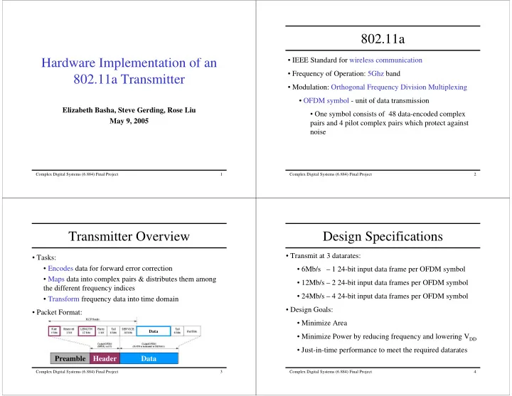
 • Design Goals: • Packet Format: • Minimize Area Data • Minimize Power by reducing frequency and lowering V DD • Just-in-time performance to meet the required datarates Preamble Header Data Complex Digital Systems (6.884) Final Project 3 Complex Digital Systems (6.884) Final Project 4

  2. Top Level Model Basic Serial Scrambler Design Input Bit • Processes 1 input bit per cycle • Simultaneously generates Convolutional Scrambler Interleaver Encoder 1 scramble sequence bit and computes 1 output bit MAC Controller Scramble Sequence Cyclic Mapper IFFT DAC Extend • Repeatedly generates a Bit 127-bit scramble sequence Send header control messages Send body control messages Send header and body data = Control Queue Output Bit Process header = Data Queue Process body Complex Digital Systems (6.884) Final Project 5 Complex Digital Systems (6.884) Final Project 6 Initial Scrambler Design Unrolled Scrambler Design • Simultaneously generates 1 For Each Message: frame of the scrambler sequence • Generates the entire 127-bit scramble sequence – 127 cycles and processes 1 frame of input • Stores the scrambler sequence to be used throughout the message data per cycle Advantage: • Updates the state of the seed • Processes 1 24-bit input frame per cycle register at end of each cycle •Advantages: Disadvantage: • Large initialization overhead is especially apparent for a • 1 cycle initialization series of very short messages • Processes 1 24-bit frame per cycle Complex Digital Systems (6.884) Final Project 7 Complex Digital Systems (6.884) Final Project 8

  3. Convolutional Encoder Design Interleaver Algorithm Serial Design Unrolled Design . . input output . . History Buffer . . • Reorders input data bits • Datarate dependent: • Interleaving Pattern • # of bits interleaved together Complex Digital Systems (6.884) Final Project 9 Complex Digital Systems (6.884) Final Project 10 Mapper Algorithm IFFT Initial Design Lookup tables Frequency domain OutputDataQ InputDataQ Input bits (1 for each rate) OFDM symbol 16-Node 16-Node 16-Node I Q Stage 1 Stage 2 Stage 3 0xA57E 0xA57E 0 0x8000 0x0000 0xA57E 0x5A7E 1 0x7FFF 0x0000 . . . . . . I Q Twiddle 0 0xA57E 0xA57E Combining Combining Multiply 1 0x5A82 0xA57E Stage 1 Stage 2 Stage . . . . Radix4 Node . . I Q 0 0x8692 0x8692 • Area = 29.12mm 2 * + Radix4 Nodes 1 0x796E 0x8692 . . 1 16 24 . . • Cycle Time = 63.18ns . . 48 768 1152 Rate Complex Digital Systems (6.884) Final Project 11 Complex Digital Systems (6.884) Final Project 12

  4. IFFT Design Exploration 1 IFFT Design Exploration 2 OutputDataQ InputDataQ OutputDataQ InputDataQ Data and 16-Node Data and Twiddle 16-Node Stage Start Twiddle Setup Stage Setup • Area = 5.19mm 2 • Area = 4.57mm 2 • Cycle Time = 30.50ns • Cycle Time = 32.89ns Complex Digital Systems (6.884) Final Project 13 Complex Digital Systems (6.884) Final Project 14 Cyclic Extender Test Strategy • Our test structure must enable us to: 64 Complex Pairs of Data – Debug each module separately First Complex Pair – Quickly verify new version of modules – Verify correctness of entire system Last 16 Complex Pairs – Measure throughput of individual modules and system as a whole 64 Complex Pairs of Data • To do this, we leveraged the framework of the Extreme Benchmark Suite (XBS) Complex Digital Systems (6.884) Final Project 15 Complex Digital Systems (6.884) Final Project 16

  5. XBS Overview XBS Overview XBS is a benchmark suite designed to measure the Device Under Test performance of highly parallel processors and custom [Bluespec] hardware implementations. Binary Binary Input Test Output Input Output Generator Harness Checker Files Files All XBS benchmarks have the following structure: [ANSI C] [Verilog] [ANSI C] Input Generator Device Device Under Test Under Test • Creates sets of test inputs to be read by test harness and [Bluespec] [Bluespec] output checker Binary Binary Binary Binary Input Test Output Input Test Output Input Output Input Output Generator Harness Checker • Generates both random and directed tests Generator Harness Checker Files Files Files Files [ANSI C] [Verilog] [ANSI C] [ANSI C] [Verilog] [ANSI C] Complex Digital Systems (6.884) Final Project 17 Complex Digital Systems (6.884) Final Project 18 XBS Overview XBS Overview Device Device Under Test Under Test [Bluespec] [Bluespec] Binary Binary Binary Binary Input Test Output Input Test Output Input Output Input Output Generator Harness Checker Generator Harness Checker Files Files Files Files [ANSI C] [Verilog] [ANSI C] [ANSI C] [Verilog] [ANSI C] Test Harness Output Checker • Encapsulates device under test • Reads in input and output files and determines if output files are correct • Reads in input files and generates output files • Usually contains an ANSI C reference version of DUT • Measures performance [throughput in bits per cycle] of • If output is incorrect, displays location of discrepancy and device under test correct value for debugging purposes Complex Digital Systems (6.884) Final Project 19 Complex Digital Systems (6.884) Final Project 20

  6. Results Evaluation Place and route results: • Our design fully conforms to the IEEE 802.11a standard 5.27 mm 2 Total Area • Our design meets timing for the 6, 12, and 24 Mbps Critical Path Delay 32.89 ns transmission rates – Total system throughput (24 Mbps) = 12 bits / cycle XBS testing results: – Clock Frequency = 30.4 MHz Throughput Module – Maximum data rate of system = 364.8 Mbps Input bits per cycle OFDM symbols per cycle Scrambler 24 24 24 1 0.5 0.25 • We can turn our timing slack into power savings by = 6 Mbps Convolutional Encoder 24 24 24 1 0.5 0.25 reducing V DD and clock frequency Interleaver 12 12 12 0.5 0.25 0.125 = 12 Mbps – Clock frequency can be reduced to 2.0 MHz Mapper 12 16 19.2 0.5 0.333 0.2 IFFT 6 12 24 0.25 0.25 0.25 = 24 Mbps Cyclic Extend 24 48 96 1 1 1 Transmitter System 6 12 12 0.25 0.25 0.125 Complex Digital Systems (6.884) Final Project 21 Complex Digital Systems (6.884) Final Project 22

Download Presentation
Download Policy: The content available on the website is offered to you 'AS IS' for your personal information and use only. It cannot be commercialized, licensed, or distributed on other websites without prior consent from the author. To download a presentation, simply click this link. If you encounter any difficulties during the download process, it's possible that the publisher has removed the file from their server.

Recommend


More recommend