~ 111111 - - PDF document

111111
SMART_READER_LITE
LIVE PREVIEW

~ 111111 - - PDF document

~ 111111 1111111111111111111111111111111111111111111111111111111111111 US008731148Bl (12) United States Patent US 8,731,148 Bl (10) Patent No.: Lavian et al. (45) Date of Patent: *May 20, 2014 (54) SYSTEMS AND METHODS FOR VISUAL 5,422,809 A


slide-1
SLIDE 1

(12) United States Patent

Lavian et al.

(54) SYSTEMS AND METHODS FOR VISUAL PRESENTATION AND SELECTION OF IVR MENU (76) Inventors: Tal Lavian, Sunnyvale, CA (US); Zvi Or-Bach, San Jose, CA (US) ( *) Notice: Subject to any disclaimer, the term of this patent is extended or adjusted under 35 U.S.c. 154(b) by 0 days. This patent is subject to a terminal dis- claimer. (21)

  • Appl. No.: 13/410,321

(22) Filed:

  • Mar. 2, 2012

(51)

  • Int. Cl.

H04M 11/00 (2006.01) (52) U.S. Cl. (58) (56) USPC .................. 379/88.18; 379/88.17; 379/88.01; 379/88.04 Field of Classification Search USPC .......... 379/88.01,88.03,88.04,88.17,88.18, 379/88.19,88.23 See application file for complete search history. References Cited U.S. PATENT DOCUMENTS

4,653,045 A 4,736,405 A 4,897,866 A 5,006,987 A 5,007,429 A 5,027,400 A 5,086,385 A 5,144,548 A 5,265,014 A 5,294,229 A 5,335,276 A 5,416,831 A 5,417,575 A 311987 Stanleyet al. 411988 Akiyama 111990 Majmudar et al. 411991 Harless 4/1991 Treatch et al. 6/1991 Baji et al. 211992 Launeyet al. 911992 Salandro 1111993 Haddock et al. 311994 Hartzell et al. 811994 Thompson et al. 511995 Chewning, III et al. 511995 McTaggart

r::l<

~

Device (Telephone)

) I

. Vis up hone

'--------1-04-;-r---' 111111 1111111111111111111111111111111111111111111111111111111111111

US008731148Bl

(10) Patent No.:

US 8,731,148 Bl

*May 20, 2014

(45) Date of Patent: EP EP

5,422,809 A 5,465,213 A 5,465,401 A 5,475,399 A 5,499,330 A 5,519,809 A 5,533,102 A 6/1995 Griffin et al. 1111995 Ross 1111995 Thompson 12/1995 Borsuk 3/1996 Lucas et al. 5/1996 Husseiny et al. 7/1996 Robinson et al.

(Continued) FOREIGN PATENT DOCUMENTS

1225754 A3 1001597 A3 7/2003 9/2003

(Continued) OTHER PUBLICATIONS

Yin, M. and Zhai, S., "The Benefits of Augmenting Telephone Voice Menu Navigation with Visual Browsing and Search," Chi'06 Pro- ceedings ofthe SIGCHI conference on Human Factors in computing systems: pp. 319-328, ACM, Montreal, Canada (Apr. 2006).

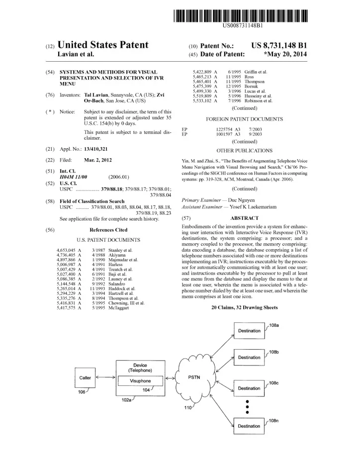
(Continued) Primary Examiner - Duc Nguyen Assistant Examiner - YosefK Laekemariam (57) ABSTRACT Embodiments of the invention provide a system for enhanc- ing user interaction with Interactive Voice Response (IVR) destinations, the system comprising: a processor; and a memory coupled to the processor, the memory comprising: data encoding a database, the database comprising a list of telephone numbers associated with one or more destinations implementing an IVR; instructions executable by the proces- sor for automatically communicating with at least one user; and instructions executable by the processor to pull at least

  • ne menu from the database and display the menu to the at

least one user, wherein the menu is associated with a tele- phone number dialed by the at least one user, and wherein the menu comprises at least one icon. 110 20 Claims, 32 Drawing Sheets 108a 108b

lr

108C

Destination I

  • 108n
slide-2
SLIDE 2

US 8,731,148 Bl

Page 2 (56) References Cited

6,463,145 Bl 1012002 O'Neal etal. 6,482,156 B2 1112002 Iliff

U.S. PATENT DOCUMENTS

6,505,146 Bl 112003 Blackmer 6,510,411 Bl 112003 Norton et al. 5,550,746 A 811996 Jacobs 6,529,500 Bl 3/2003 Pandharipande 5,572,581 A 1111996 Sattar et al. 6,560,320 Bl 5/2003 Paleiov et al. 5,585,858 A 1211996 Harper et al. 6,603,840 B2 8/2003 Fellingham et al. 5,586,235 A 1211996 Kauffman 6,606,611 Bl 8/2003 Khan 5,588,044 A 1211996 Lofgren et al. 6,606,741 B2 8/2003 Kojima et al. 5,592,538 A * 111997 Kosowsky et al . ......... 379193.08 6,636,835 B2 10/2003 Ragsdale et al. 5,606,361 A 211997 Davidsohn et al. 6,653,930 Bl 1112003 Bonomo etal. 5,633,909 A 511997 Fitch 6,658,389 Bl 12/2003 Alpdemir 5,633,916 A 511997 Goldhagen et al. 6,705,869 B2 3/2004 Schwartz 5,657,221 A 811997 Warman et al. 6,714,519 B2 3/2004 Luzzatti et al. 5,689,648 A 1111997 Diaz et al. 6,731,625 Bl 5/2004 Eastep et al. 5,724,412 A 311998 Srinivasan 6,754,181 Bl 6/2004 Elliott et al. 5,739,814 A 411998 Ohara et al. 6,788,770 Bl 912004 Cook et al. 5,740,549 A 411998 Reilly et al. 6,791,583 B2 912004 Tang et al. 5,768,142 A 611998 Jacobs 6,816,580 B2 1112004 Timmins 5,790,652 A 811998 Gulleyet al. 6,820,037 B2 1112004 Simon 5,794,205 A 811998 Walters et al. 6,820,062 Bl 1112004 Gupta et al. 5,796,806 A 811998 Birckbichler 6,826,194 Bl 1112004 Vered et al. 5,802,283 A 911998 Gradyet al. 6,829,368 B2 1212004 Meyer et al. 5,802,526 A 911998 Fawcett et al. 6,856,673 Bl 212005 Banks et al. 5,807,336 A 911998 Russo et al. 6,862,713 Bl 3/2005 Kraft et al. 5,819,225 A 1011998 Eastwood et al. 6,865,268 Bl 3/2005 Matthews et al. 5,822,404 A 1011998 Cave 6,885,737 Bl 4/2005 Gao et al. 5,822,405 A 1011998 Astarabadi 6,889,195 B2 5/2005 Strandberg 5,838,682 A 1111998 Dekelbaum et al. 6,920,205 B2 712005 Hahn et al. 5,838,775 A 1111998 Montalbano 6,920,425 Bl 712005 Will et al. 5,867,816 A 211999 Nussbaum 6,920,431 B2 712005 Showghi et al. 5,873,068 A 211999 Beaumont et al. 6,937,705 Bl 8/2005 Godfrey et al. 5,885,083 A 311999 Ferrell 6,968,506 B2 1112005 Yacovone et al. 5,885,245 A 311999 Lynch et al. 6,990,455 B2 112006 Vozick 5,890,123 A 311999 Brown etal. 7,020,609 B2 3/2006 Thrift et al. 5,892,813 A 411999 Morin et al. 7,027,990 B2 * 4/2006 Sussman .................... 704/270.1 5,907,793 A 511999 Reams 7,036,128 Bl 4/2006 Julia et al. 5,912,952 A 611999 Brendzel 7,039,589 B2 5/2006 Whitham 5,913,195 A 611999 Weeren et al. 7,047,196 B2 5/2006 Calderone et al. 5,920,477 A 711999 Hofiberg et al. 7,065,188 Bl 6/2006 Mei etal. 5,937,040 A 811999 Wrede etal. 7,068,643 Bl 6/2006 Hanunond 5,940,488 A 811999 DeGrazia et al. 7,092,738 B2 8/2006 Creamer et al. 5,948,040 A 911999 DeLorme et al. 7,100,118 Bl 8/2006 Klask 5,956,034 A 911999 Sachs et al. 7,130,391 B2 10/2006 Janakiraman et al. 5,982,875 A 1111999 Lieben et al. 7,136,480 B2 1112006 Mason 5,987,103 A 1111999 Martino 7,139,591 B2 1112006 Callaghan et al. 6,009,398 A 1211999 Mueller et al. 7,145,902 B2 12/2006 Schindler et al. 6,014,428 A 112000 Wolf 7,146,321 B2 12/2006 Cyr et al. 6,020,915 A 212000 Bruno et al. 7,149,549 Bl 1212006 Ortiz et al. 6,049,779 A 4/2000 Berkson 7,159,008 Bl 112007 Wies et al. 6,055,513 A 4/2000 Katz et al. 7,177,814 B2 212007 Gong et al. 6,062,863 A 5/2000 Kirksey et al. 7,180,889 Bl 212007 Kung et al. 6,088,429 A 7/2000 Garcia 7,180,985 B2 212007 Colson et al. 6,088,712 A 7/2000 Huang et al. 7,181,401 B2 212007 Johnson et al. 6,091,805 A 7/2000 Watson 7,181,502 B2 212007 Incertis 6,091,956 A 7/2000 Hollenberg 7,188,352 B2 3/2007 Nathan et al. 6,104,790 A 8/2000 N arayanaswami 7,203,517 B2 4/2007 Shimoda et al. 6,144,848 A 1112000 Walsh etal. 7,206,745 B2 4/2007 Sarukkai et al. 6,148,065 A 1112000 Katz 7,206,809 B2 4/2007 Ludwig etal. 6,169,734 Bl 112001 Wilson 7,209,124 B2 4/2007 Hunt et al. 6,212,547 Bl 4/2001 Ludwig etal. 7,213,061 Bl 5/2007 Hite et al 6,228,921 Bl 5/2001 Kasemann et al. 7,215,743 B2 5/2007 Creamer et al. 6,229,694 Bl 5/2001 Kono 7,216,348 Bl 5/2007 deCarmo 6,230,197 Bl 5/2001 Beck et al. 7,225,409 B 1 5/2007 Schnarel et al. 6,259,444 Bl 7/2001 Palmer et al. 7,225,455 B2 5/2007 Bennington et al. 6,263,064 Bl 7/2001 O'Neal et al. 7,228,492 Bl 6/2007 Graham 6,273,726 Bl 8/2001 Kirksey et al. 7,231,636 Bl 6/2007 Evans 6,321,198 Bl 1112001 Hanket al. 7,231,656 Bl 6/2007 Nathan 6,335,678 Bl 112002 Heutschi 7,240,006 Bl 7/2007 Brocious et al. 6,366,650 Bl 4/2002 Rhie et al. 7,240,289 B2 7/2007 Naughton et al. 6,373,817 Bl 4/2002 Kung etal. 7,246,063 B2 7/2007 James et al. 6,400,807 Bl 6/2002 Hewitt et al. 7,248,885 B2 7/2007 Benco et al. 6,405,033 Bl 6/2002 Kennedy, III et al. 7,250,939 B2 7/2007 Lira 6,408,301 Bl 6/2002 Patton et al. 7,254,227 B2 8/2007 Mumicketal. 6,427,063 Bl 7/2002 Cooket al. 7,265,861 Bl 912007 Ranalli et al. 6,445,694 Bl 912002 Swartz 7,266,185 B2 912007 Trandel et al. 6,449,595 Bl 912002 Arslan et al. 7,266,186 Bl 912007 Henderson 6,456,706 Bl 912002 Blood et al. 7,266,499 B2 912007 Surace et al. 6,460,057 Bl 1012002 Butler et al. 7,272,222 B2 912007 Joseph et al.

slide-3
SLIDE 3

(56) References Cited

US 8,731,148 Bl

Page 3

1012008 Conway et al. ............ 379/88.03 1012008 Price

u.s. PATENT DOCUMENTS

2008/0240376 Al * 2008/0250334 Al 2009/0041215 Al 2009/0116414 Al 2009/0136014 Al 200910154666 Al 200910202050 Al 200910207980 Al 200910207996 Al 200910225788 Al 200910228908 Al 2009/0276441 Al 200910276708 Al 200910280863 Al 200910285380 Al 201010007028 Al 2010/0021030 Al 201010049654 Al 2010/0087175 Al 2010/0100377 Al 2010/0166158 Al 2010/0172481 Al 2010/0189250 Al 201110009096 Al 201110014952 Al 201110060683 Al 201110091021 Al 201110099116 Al 201110276408 Al 201210063574 Al 212009 Schmitt et al. 5/2009 Or et al. 5/2009 Bigue et al. 6/2009 Rios et al. 8/2009 Berger et al. 8/2009 Berger et al. 8/2009 Berger et al. 912009 Kephart et al. 912009 Margis et al. 7,272,497 B2 7,277,854 B2 7,280,097 B2 7,280,646 B2 7,280,651 B2 7,286,990 Bl 7,289,608 B2 7,289,904 B2 7,299,405 Bl 7,303,121 B2 7,319,477 B2 7,324,947 B2 7,328,239 Bl 7,330,890 Bl 7,353,016 B2 7,392,193 B2 7,398,215 B2 7,406,413 B2 7,412,533 Bl 7,433,452 B2 7,440,898 Bl 7,450,112 B2 7,466,803 B2 7,492,883 B2 7,539,484 B2 7,546,143 B2 7,584,249 B2 7,606,741 B2 7,646,858 B2 7,693,720 B2 7,720,091 B2 7,729,490 B2 7,757,173 B2 7,809,376 B2 7,813,485 B2 7,843,899 B2 7,864,944 B2 7,908,381 B2 7,966,188 B2 8,000,454 Bl 8,023,624 B2 8,054,952 Bl 8,155,280 Bl 8,160,215 B2 200210055844 Al 200210147986 Al 2003/0005126 Al 2003/0007625 Al 2003/0033382 Al 2003/0074198 Al 2003/0112931 Al 2004/0034561 Al 2004/0044739 Al * 2004/0122941 Al 2004/0198316 Al 2004/0204116 Al 2004/02611 00 Al * 2005/0004977 Al 2005/0055310 Al 2006/0203977 Al 2006/0239422 Al 2006/0259424 Al 2006/0262921 Al 2006/0285662 Al 2007/0026852 Al 2007/0032247 Al 2007/0038513 Al 2007/0094109 Al 2007/0123223 Al 2007/0239537 Al 2007/0243887 Al 2007/0298776 Al 2008/0066015 Al 2008/0095330 Al 2008/0226042 Al 912007 Koshiji et al. 1012007 Bennett et al. 1012007 Chen et al. 1012007 Urban et al. 1012007 Anderson 1012007 Edmonds et al. 1012007 Kwnhyr 1012007 Uyeki 1112007 Lee et al. 1212007 Martinez 112008 Katz 112008 Jordan et al. 212008 Berberian et al. 212008 Partovi et al. 4/2008 Roundtree et al. 6/2008 Mault 7/2008 Mesbah et al. 7/2008 Geppert et al. 8/2008 Johnson et al. 1012008 Taylor et al. 1012008 Eberle et al. 1112008 Shneidman 1212008 Burg et al. 212009 Kwnhyr 5/2009 Roundtree 6/2009 Nelson et al. 912009 Mununick et al. 1012009 King et al. 112010 Salafia et al. 4/2010 Kennewicketal. 512010 Faber et al. 6/2010 Hemm et al. 7/2010 Beaman 1012010 Letourneau et al. 1012010 Yinetal. 1112010 Burritt 112011 Khouri et al. 3/2011 Koch et al. 6/2011 Ativanichayaphong et al. 8/2011 Or-Bach et al. 912011 Kargman et al. 1112011 Or-Bach et al. 4/2012 Or-Bach et al. 4/2012 Or-Bach et al. 5/2002 L'Esperance et al. 1012002 Michael et al. 112003 Schwartz et al. 112003 Pines et al. 212003 Bogolea et al. 4/2003 Sussman 6/2003 Brown et al. 212004 Smith 3/2004 Ziegler .......................... 7091213 6/2004 Creamer et al. 1012004 Johnson 1012004 Ben Efraim et al. 1212004 Huber et al. .................... 725/32 112005 Roberts et al. 3/2005 Drewett et al. 912006 Erhart et al. 1012006 Rinaldo et al. 1112006 Turcotte et al. 1112006 Eppel et al. 1212006 Yin et al. 212007 Logan et al. 212007 Shaffer et al. 212007 Flax et al. 4/2007 Perry 5/2007 Letourneau et al. 1012007 Protheroe et al. 1012007 Bandhole et al. 1212007 Arlene 312008 Blankenhorn 4/2008 Jin et al. 912008 Singh EP EP EP EP EP JP WO WO WO WO WO WO WO WO WO WO WO WO WO WO WO WO 1112009 Malik 1112009 Smith et al. 1112009 Shin et al. 1112009 Chen et al. 112010 Fachmann et al. 112010 Collins et al. 212010 Pilo 4/2010 Roundtree 4/2010 Madhavapeddi et al. 7/2010 Costello et al. 7/2010 Canu et al. 7/2010 Williams et al. 112011 Rotsztein et al. 112011 Minton 3/2011 Salmon Rock et al. 4/2011 Adkar et al. 4/2011 Gabel 1112011 Toole 3/2012 Or-Bach et al.

FOREIGN PATENT DOCUMENTS

1351477 Al 1120954 A3 1545101 A3 774853 Bl 1874018 Al 2004274425 A 9848551 A3 9819259 Al 9840826 A3 9856158 A3 0131497 Al 0157851 Al 0165871 Al 9820409 A8 0217604 Al 2004049306 Al 2004064299 A3 2007012831 Al 2007081929 A3 2008086320 Al 2009006173 A3 2009100477 Al 10/2003 6/2005 1212005 512006 112008 912004 4/1998 5/1998 12/1998 3/1999 5/2001 8/2001 912001 1112001 212002 6/2004 7/2005 212007 112008 7/2008 3/2009 8/2009

OTHER PUBLICATIONS

Darnhuis, M., et aI., "A Multimodal Consumer Information Server with IVR Menu," 2nd IEEE Workshop on Interactive Voice Technol-

  • gy for Telecommunications Applications (IVTTA94): pp. 73-76,

Kyoto, Japan (Sep. 1994). Shah, S.AA., et aI., "Interactive Voice Response with Pattern Recog- nition Based on Artificial Neural Network Approach," International Conference on Emerging Technologies: pp. 249-252, (Nov. 2007). Trihandoyo, A., et aI., "A real-time speech recognition architecture for a multi-channel interactive voice response system," International Conference on Acoustics, Speech, and Signal Processing vol. 4: pp. 2687-2690,(1995). Hattori, S., et al., "A multimedia intelligent message communication system for distributed coordination environments," Electronics & Communications in Japan, Part I-Communications, vol. 76, No.1,

  • pp. 11-23 (1993).

Patent abstracts of Japan, vol. 097, No. 001, Jan. 31,1997 & JP 08 242307 A (Canon Inc), Sep. 17, 1996. Kalva, H., et al., "Delivering Object-Based Audio-Visual Services," IEEE Transactions on Consumer Electronics, vol. 45, No.4, pp. 1108-1111, (1999).

slide-4
SLIDE 4

US 8,731,148 Bl

Page 4 (56) References Cited OTHER PUBLICATIONS

Schmandt, "Phoneshell: the telephone as computer terminal," Pro- ceedings offirstACM International Conference on Multimedia, Ana- heim, CA, US, pp. 373-381, (1993). Himberg, J., et ai., "Time Series Segmentation for Context Recogni- tion in Mobile Devices", IEEE, 203-210, (2001). Chris Schmandt and Stephen Casner, "Phonetool: Integrating Tele- phones and Workstations," IEEE Communication Society, Nov. 27-30, pp. 0970-0974, (1989). Basinger, R. G., et al., "Calling Card Service-Overall Description and Operational Characteristics", The Bell System Technical Jour- nal, (1982). Cadiz et ai. "Designing and Deploying an Information Awareness interface" CSCW'02, Nov. 2002, ACM, pp. 314-323. Corcoran et ai. Disclose "User interface technologies for home appli- ances and networks", IEEE Trans. Consumer Elect; pp. 679-685, (1998). Nancy Friedrich, "Graphical-User-Interface Module Eases Integra- tion," Wireless Systems Design, Oct. 2004, 1 page. Balachandran, R., et ai., "Dialog System for Mixed Initiative One- Turn Address entry and Error Recovery," Proceedings of SIGDIAL 2009, the lOth Annual Meeting of the Special Interest Group in Discourse and Dialogue, pp. 152-155, Queen Mary University of London, Association of Computational Logistics, (2009).

*

cited by examiner

slide-5
SLIDE 5

u.s. Patent

May 20,2014 Sheet 1 of 32

US 8,731,148 Bl

CG

.0

C

00 00 00 00

......

......

...... ......

c c c c

+=' +=' +=' +='

CG CG CG CG

C C C

  • • •

C +=' +=' +=' +='

en en en en

0) 0) 0) 0)

..-

0) 0)

"'i;j"

~

§

c

......

.- .s::

.s::

>c.

c.

0) 0) ::J

0-

en

~

:>

CG

  • N

......

I

OJ

ID co

(,)

......

slide-6
SLIDE 6

Network

t{

')1 Gateway

112

1

Device (Computer + VOIP) Caller <

>\

Visuphone

I

PSTN

10R./

104b .J 102b

FIG.1B

116 108a Destination

/1

Destination V 108b Destination V 108c

  • 108n

Destination r

~

7Jl

  • ~

~ ~

~ = ~

~

~

N

~o

N

....

.j;o.

rFJ

=-

('D ('D

.....

N

....

(.H

N

d

rJl

",010

  • ....l

W

!"""

"""'"

~ 010

=

"""'"

slide-7
SLIDE 7

112 Network Device (Smartphone) Caller I

( ) 1\

Visuphone 106 111 1047 Cellular Network

£'

">1 Gateway

PSTN

/110

FIG.1C

116 108a Destination

/ 1 Destinat"

I r 108b ,

Ion

1.1

\

I

Destination

  • Destination

108c 108n

~

7Jl

  • ~

~ ~

~ = ~

~

~

N

~o

N

  • ....

.j;o.

rFJ

=-

('D ('D

.....

(.H

  • ....

(.H

N

d

rJl

",010

  • ....l

W """'" '" """'"

~ 010

=

"""'"

slide-8
SLIDE 8

108a ./ Destination Board

I

r

202a Number r 222a

,------------------------------------------ -~-

  • ------ftiain-nn-enii----------------- -------------------------------,

Press 2 for Press 3 204a Pizza Orde 206a Order Status Press 0 for main menu" 220aJ 210a

~

__

  • L-_~

212a Press 2 for ress 1 to talk to Non-Veg the Executive

~Pres

1 for 208a J I Veg

, [?(J ,

V

218a Press 1 for Press 2 for 216a Home Take : 214a Delivery Away

,

, ,

I ~

_____________________________________________________ _______________

_

,--------------------------------------------------------------------------------------------

FIG.2A

~

7Jl

  • ~

~ ~

~ = ~

~

~

N

~o

N

  • ....

.j;o.

rFJ

=-

('D ('D

......

.j;o.

  • ....

(.H

N

d

rJl

QO

~ W

"""'" '" """'"

~

QO

=

"""'"

slide-9
SLIDE 9

102b

  • ~-:

208b

,

: 214b , , ,

,

Pizza Order

204b ./ I 2

Board number 1

210b

V~g

I I

Non;Veg

206b

Order Status

3

Talk to Executive 1

212b,

Home Delivery 1 Take Away

2

216b

~-

2-2b-~-

  • __
I

108a

Destination

110

1

1161 Gateway I

!

( )

  • FIG. 28

~

7Jl

  • ~

~ ~

~ = ~

~

~

N

~o

N

  • ....

.j;o.

rFJ

=-

('D ('D

.....

Ul

  • ....

(.H

N

d

rJl

QO

~ W

"""'" '" """'"

~

QO

=

"""'"

slide-10
SLIDE 10

102b Device

  • ~

Board number 1 Pizza Order 204c Veg 208c ../ I t3' 1

i<

2

210c Non-Veg

'$:2

::>i

206c rder Statu

  • 3

Talk to I __ 212c Executive , 1 Home Delivery

214c.J I Q

1 Take Away 216c

J\

2

._------ 222c-T--------------------

  • _____
1

108a Destination 110./ \.

r

1

116 1 Gateway I

~

< >Gatw, \

J

FIG.2C

~

7Jl

  • ~

~ ~

~ = ~

~

~

~ N

~

N

....

.j;o.

rFJ

=-

('D ('D

.....

0\

....

(.H

N

d

rJl

QO

~ W

"""'"

~

~

QO

=

"""'"

slide-11
SLIDE 11

102b 204c 226 224 Device Welcome to our Pizza place. Please press 1 to check your order status

  • r press 2 to make a new order

rder Statu 1 206c Please press 1 for vegetarion order or press 2 for non-vegetarian pizza order 222 208c \.J Veg

tJ1

Non-Veg V 210c

'$:2

  • ~-

222c

FIG.2D

~

7Jl

  • ~

~ ~

~ = ~

~

~

N

~O

N

  • ....

.j;o.

rFJ

=-

('D ('D

.....

  • ....l
  • ....

(.H

N

d

rJl

QO

~ W

"""'" '" """'"

~

QO

=

"""'"

slide-12
SLIDE 12

Device

(ComputerISmartphone)

j302

4

1<

1

Radio Display

.-

Interface Central Processing Unit

I~

.....

Network

.-

Interface

304) 324 .J

102a

t'

j306

Memory

I I

Visuphone I nputlOutput

"

104

.-

interface Visual Menu Database I~ 308 Other Applications 310 4.

FIG.3A

(::

If

312

¢

I

Gatewa

If

314

¢

"

_ .....

Network

.-

112

V

316

V

  • '"

Memory

.-

Card

"

Lr- ~I

Keyboard ~

"

USB

., '--.-71

Mouse 1

11

  • 324

~

7Jl

  • ~

~ ~

~ = ~

~

~

N

~o

N

  • ....

.j;o.

rFJ

=-

('D ('D

.....

QO

  • ....

(.H

N

d

rJl

QO

~ W

"""'" '" """'"

~

QO

=

"""'"

slide-13
SLIDE 13

Device

(ComputerlSmartphone)

;302

4

I

I~

  • -"

Radio Display

,

Interface 304

f

324 Central Processing Unit I~

f

  • ""-

Network Interface Memory

/

102a VOIP Application 340

I

Input/Output

I

Visuphone

~

104

I~

interface

(

Visual Menu Database 308

,..,

306 Other Applications 310

  • FIG. 38

b

v

312

¢ 1

Gateway I

V

314 ~y-~

/

~

Network

"

/

If

316 112 3' " Memory V

...

Card 3:

~I

Keyboard r

" Lt-

3

  • ""-

USB

"..

L..- ~I

Mouse I

11

  • 324

~

~

7Jl

  • ~

~ ~

~ = ~

~

~

N

~o

N

  • ....

.j;o.

rFJ

=-

('D ('D

.....

\0

  • .....

(.H

N

d

rJl

QO

~ W

"""'" '" """'"

~

QO

=

"""'"

slide-14
SLIDE 14

u.s. Patent

  • .

~

Q)

Q) c:

u.,g

.-

0-

>t

Q) ro

  • E

C/)

  • ~(

N

  • "'¢
  • 0>

co

I";-

co

It)

"'t

('t')

N

May 20,2014 Sheet 10 of 32

co co

  • "'¢

"'¢

  • ~-r_>_

"' __

>- ..c

0:::"

0>-

a.ffi

_Q.

UE

:::lo

"C u

e

Q.~ ~><

Z

US 8,731,148 Bl

  • N

('t')

.GG

GE]

GB

GG

BG

BB.

l l

.............. __ .. _ .. ___________________________ .. _ ...... _ .. _ .. ____ ... _ .. _ .......... __ ........ _ ...................... __ ........
  • _
.............................
  • -...........
_1

U N

  • 'I"""
slide-15
SLIDE 15
  • FIG. 5

116

IGa~wa+~

02 518

Mouse ~

520

Keyboard r

522

Speaker ~

~J524 ~

~523 Microphone

~

7Jl

  • ~

~ ~

~ = ~

~

~

N

~o

N

  • ....

.j;o.

rFJ

=-

('D ('D

.....

.... ....

  • ....

(.H

N

d

rJl

QO

~ W

"""'" '" """'"

~

QO

=

"""'"

slide-16
SLIDE 16

u.s. Patent

May 20,2014 Sheet 12 of 32

GGGG [IJ

GBBB

GGGEJ [[J

'""\

  • --------------------------------------------y---------------

'\

  • q-
  • co

"

co

  • co

,-~-

___________________________________________________ J

.c

N

  • ~

co

  • co

"

US 8,731,148 Bl

slide-17
SLIDE 17

u.s. Patent

a>

()

">

a>

Cl

May 20,2014

s- a>

en

3:

e

CO

.c

N

  • "I'""

a>

0')

co

c-

.c

~

"

N

I'-

Sheet 13 of 32

US 8,731,148 Bl

ts

........

a>

c: c:

CD

O IJ..

"

co

I'-

~ 0

I'-

slide-18
SLIDE 18

u.s. Patent

May 20,2014 Sheet 14 of 32

US 8,731,148 Bl

00

CD ~

N 00

00 00 00

'----

'" '" '"

en

c:

:;::;

C1:S

02

c..

c.

«

'-

Q)

.c:

  • E

Q)

  • en

~

CO

>-

~

(f)

C1:S

.

0)

Q)

~

C.9 >

"E

c:

0C: :;::;

Cl

C1:S

LL

~

:c

Q)

c.

Q)

c: .c:

C.

::::s

en

:>

~g

"

00

~ 0

T""

slide-19
SLIDE 19

~

VisuPhone

7Jl

  • r

902

~

Detection Module

~ ~

~ = ~

Search Module

r

904

~

r

906

~

~

Display Module

N

~o

N

....

r

90B

.j;o.

Connection Module

104

~I

rFJ

r

910 =-

('D

Voice Module

('D

.....

....

Ul

....

r

912

(.H

N

Advertisement Module Update Module

r

914 d

rJl

r

916

QO

Customization Module

~ w

"""'" '" """'"

  • FIG. 9

~

QO

=

"""'"

slide-20
SLIDE 20

Device Visual Menu Database 308 102 1004 .. Remote Repository

t

1002 {m~emote Server I

('

")

1008

1

Computer Network

t

Gateway 1006

  • FIG. 10

108a

.L 1012a

menu Repository

t

Destination 1010

PSTN 1012n Audible IVR menu Repository

t

Destination

~

7Jl

  • ~

~ ~

~ = ~

~

~

N

~o

N

  • ....

.j;o.

rFJ

=-

('D ('D

.....

....

0\

  • ....

(.H

N

d

rJl

QO

~ W

"""'" '" """'"

~

QO

=

"""'"

slide-21
SLIDE 21

u.s. Patent

co

00

~

c::

:;::::;

CO

c::

~ Q)

Q

CO

00

~

  • 1:5

Q)

N c:: c::

~

(,)

~ ~

May 20,2014 Sheet 17 of 32

.0

00

~

qBO~

Ol pJeMJo.::J 'Z

~ 0

~ ~

~

~

~ "

  • ::f!!

."tii>Q

~"

qj

~

~

0,0

~

CO 0,'

  • S

b'

~

~

Q)

c::

  • ~1 -ao
:J~

(J)

:>

N

  • ~

~

§

(j

~'

c::

:;::::;

CO

c::

:;::::;

(J)

Q)

Q

US 8,731,148 Bl

~ ~ .

(9

u..

slide-22
SLIDE 22

u.s. Patent

v

  • N

~

May 20,2014

)

<

)

Sheet 18 of 32

E

Q)

"'C

  • :2

>.

CI3

3:

Q)

  • CI3

C>

co

~

N

~

~ ~

~ Q)

z

US 8,731,148 Bl

~

C>

IJ..

slide-23
SLIDE 23

u.s. Patent

May 20,2014

  • ....

ctS Q) Q)

C:U"'O Q) "~

"5

x Q) e

WCl)a..

Sheet 19 of 32

US 8,731,148 Bl

c:

N

:.;::;;

~

ctS

('t')

c:

:.;::;;

~

en

Q)

Cl

slide-24
SLIDE 24

1408

./

'-

Add-On

1406 1402 1404

FIG.14A

1414 _1420 1412 1422

( L

~

1418

I!~_~

__

((

  • FIG. 148

1426 1428 1430

~

CJ

1424 1432 )~ \~

.J

r(

/

Add-On

FIG.14C

~

7Jl

  • ~

~ ~

~ = ~

~

~

N

~o

N

  • ....

.j;o.

rFJ

=-

('D ('D

.....

N

  • ....

(.H

N

d

rJl

QO

~ W

"""'" '" """'"

~

QO

=

"""'"

slide-25
SLIDE 25

u.s. Patent

1502 May 20,2014 Sheet 21 of 32

C

__

s-,.-tart_)

\lI

US 8,731,148 Bl

Detect phone number of a destination dialed from a device 1504 Search for IVR information in visual menu database on the device

C0 Yes

Is a visual menu for destination available in visual menu 1508 1510 1512 1516 database? Display the visual menu and associated ~ information

L..----....--------l

Detect input from caller on the visual menu Connect to the destination based on inputs from the caller No ~

:>------7G

Maintain the connection till caller or destination disconnects

FIG.15A

slide-26
SLIDE 26

u.s. Patent

May 20,2014 Sheet 22 of 32

US 8,731,148 Bl 1518

&

Connect the device to a remote

~

G repository

'---------,--------'

1522

  • Yes

1526

Update the visual menu database from remote repository Is the visual menu available in updated visual menu database? Update the remote repository ./ ~

I....-----r---------''\J

C

___

Sto_

p --.--)

  • FIG. 158
slide-27
SLIDE 27

u.s. Patent

May 20,2014 Sheet 23 of 32 1530 Provide the dialed number as a destination to remote repository

US 8,731,148 Bl No

C

__

S_top_)~-, FIG.15C

slide-28
SLIDE 28

u.s. Patent

1558

May 20,2014 Sheet 24 of 32 Connect device to a remote repository Is there an updated version of the visual menu in the remote repository? Yes

8

FIG.15D

US 8,731,148 Bl No

slide-29
SLIDE 29

1604 1610 1612 Device Memory Database Construction System 1606 Records Database 1608

t

~

Processor

t

~

Network Interface

1<

7\

1602

  • FIG. 16

1618

'f

1620a Destination 1620b

:;" I Destination I,

<

~.

1

  • 1620n

I

Destination lr Gateway 1616

~

7Jl

  • ~

~ ~

~ = ~

~

~

N

~o

N

  • ....

.j;o.

rFJ

=-

('D ('D

.....

N

Ul

  • ....

(.H

N

d

rJl

QO

~ W

"""'" '" """'"

~

QO

=

"""'"

slide-30
SLIDE 30

Database Construction System

1;1720

Database Construction Agent

r

1606 1;1708

Personalization Module

r

Download Module

r

1710

FIG.17A

~

7Jl

  • ~

~ ~

~ = ~

~

~

N

~o

N

  • ....

.j;o.

rFJ

=-

('D ('D

.....

N

0\

  • ....

(.H

N

d

rJl

QO

~ W

"""'" '" """'"

~

QO

=

"""'"

slide-31
SLIDE 31

Database Construction Agent

1722 "- Targets List Module

( )

::u

I

CD

"'C

IVR Tracking Module

en

;::;:

1726 ~ IVR Logic Module

I

  • <

()

1720

::s

.,L

1728 '1 Tree storage Module

I~ ::s

..... CD

.,.

Sl.

cr

1730 "'1

I(

::s

Dialog Module

  • -'"

s::

...

c..

1732 \...

c:

Speech Recognition

CD

Module 1734 "'--i Response Module

I

~

1738 1736 "i VOIP Connection Module I

~1724

I I I

\I

I I I
  • --,

Destination I< i

>1

VOIP Application r 1740

l _____________________________________________________ ~-J

FIG.17B

....

Records

;7

Database

(

1608

~

7Jl

  • ~

~ ~

~ = ~

~

~

N

~o

N

  • ....

.j;o.

rFJ

=-

('D ('D

.....

N

  • ....l
  • ....

(.H

N

d

rJl

QO

~ W

"""'" '" """'"

~

QO

=

"""'"

slide-32
SLIDE 32

Database Construction Agent

1722 '-

Targets List Module

( )

::::0

I

(I)

"C

IVR Tracking Module

en

;:::;:

1726 ~

IVR Logic Module

I

  • <

()

1720

:::J

1728 "'1

Tree storage Module

1/

:::J

...

(I)

~

~ o·

1730 "1

I~

:::J

Dialog Module

...

s:

~

a.

1732 \...

c::

Speech Recognition

(I)

Module

1734 ~

Response Module

I

~ 1738 1737 '1 IVR Connection Module I

~1724

'v

[- Destination

FIG.17C

L.. "-

Records

,

."

Database

(

1608 ~

7Jl

  • ~

~ ~

~ = ~

~

~

N

~o

N

  • ....

.j;o.

rFJ

=-

("D ("D

.....

N

QO

  • ....

(.H

N

d

rJl

QO

~ W

'"'""

'"

'"'""

~

QO

=

'"'""

slide-33
SLIDE 33

u.s. Patent

May 20,2014 Sheet 29 of 32

c_---,Star--rt

  • -)

1802 \J'---___

Jr--__

  • ----'

L

Connect to a destination

t

1804 Analyze a first level of the audible IVR menu 1806 Store the information regarding the audible IVR menu in a database

No

1810\J,

..... ____

  • --..

____

  • ---I

L

Analyze the sub-menus

t

1812 Store the information regarding the sub-menus in the database

'--------3>(

__

S_to p_)

  • FIG. 18

US 8,731,148 Bl

Yes

slide-34
SLIDE 34

Category A r--7

1904

~

Category B

1906

IVR Categories

,.--

Category C

  • 7

1908

Category D ~

1910

,

Dial Tone Selection

""

Starting Questions

....

and

  • ;;>

Dial Tone Selection Personal Information

"-

and

./

Dial Tone Selection Dial Tone Selection

....

and/or

  • -;7

Natural Language Selection

  • FIG. 19

~

7Jl

  • ~

~ ~

~ = ~

~

~

N

~o

N

  • ....

.j;o.

rFJ

=-

('D ('D

.....

(.H

  • ....

(.H

N

d

rJl

QO

~ W

"""'" '" """'"

~

QO

=

"""'"

slide-35
SLIDE 35

u.s. Patent

2002 2004a 2006a 2008a 2010a 2012a May 20,2014 Sheet 31 of 32

US 8,731,148 Bl

~,- __

R_e_c_or_d_D_a_t_ab,-, a_s_e_c_o_n_te_n_t

_____

J

J J

.-/ .-/

  • F
I I I

Y

Please enter invoice number

t

Please enter the payment amount

~

Please choose your payment card:

Pre~1fur~SAor2furMa~e~a~

t

Please say or enter your Credit Card number

'II

Please enter your Credit Card expiry date

FIG.20A

slide-36
SLIDE 36

u.s. Patent

May 20,2014 Sheet 32 of 32

US 8,731,148 Bl Payment Form for ABC

2014

r-------------------------------------------------

1 1

: Please enter invoice number: : 2004b ) I

Ii

1 1 I ________________________________________________ J

1-------------------------------------------------

1 1 1

Please enter the payment amount :

2006b) I

I i

1 1 I ________________________________________________ J

1------------------------------------------------,

1 1

: Please choose your payment card: :

1 1

2008b J1 ~ VISA 0 MasterCard

!

1 1 L ________________________________________________ _

r-------------------------------------------------

1 1

: Please enter your Credit Card number :

2010b) I

I i

1 1 I ________________________________________________ J

r-------------------------------------------------

: Please enter your Credit Card expiry date :

1 1

2012b) I

I i

1 1

: ________________________________________________ J

2016 i Submn J

  • FIG. 208
slide-37
SLIDE 37

US 8,731,148 Bl 1

SYSTEMS AND METHODS FOR VISUAL PRESENTATION AND SELECTION OF IVR MENU FIELD OF THE INVENTION The invention relates to Interactive Voice Response (IVR) system and more specifically the invention relates to visual selection of IVR option from a caller device. BACKGROUND OF THE INVENTION Interactive Voice Response (IVR) technology is generally used to detect voice and key inputs from a caller. Various

  • rganizations such as banks, insurance companies, and other

service providers use IVR technology to manage calls from their customers. Typically, IVR systems are used by organi- zations that have high call volumes. An objective for imple- menting the IVR systems is to provide the customers with a quick and good experience. Moreover, the cost of providing the services is reduced. Generally, when the caller calls a destination, such as a bank, an automated audio menu is played. The audio IVR menu can contain instructions to provide instant services such as account balance inquiry when the destination is a bank. Further, audio menu can provide options for the caller to connect to a desired end inside the destination. For example, the menu may direct the caller to press various keys on a telephone to connect to a particular department or agent. The audio IVR menu is designed specific to a destination. There- fore, each destination or organization may have different IVR

  • menus. Further, the IVR menu in an organization can

be based

  • n the type of departments, type of services, customer care

executives or agents and so forth. For example, an IVR menu

  • f

a bank may include options related to the account details of the caller, while an IVR menu of a pizzeria may contain

  • ptions to order or select a pizza.

Typically, the caller calling the destination may have to listen and follow instructions on the menu to get a desired response or a function performed. Therefore, the process can be time consuming. Moreover, in case the caller provides an incorrect input, the complete process may have to be

  • repeated. Furthermore, the IVR menu for an organization

may be updated or changed regularly. For example, extension numbers inside an organization may be changed and corre- spondingly, the extension numbers associated with the IVR menu may be updated. As a result, a frequent caller may not be able to reach a desired end by remembering a combination

  • f
  • numbers. Therefore, the caller may become frustrated with

the IVR systems. Some prior art try to address this problem by providing visual form of IVR. These prior arts display the IVR menu graphically on a caller device. U.S. Pat. No. 7,215,743 assigned to International Business Machines Corporation and

2

2006 discloses sending digital signals from the destination to the caller device. Thereafter, the digital signals are processed by the caller device for presenting a visual display of the IVR

  • menu. These techniques therefore, require each destination to

set-up hardware, software and other facilities to be deployed for providing visual IVR servers. Another existing technique as disclosed in U.S. Pat. No. 6,560,320 assigned to International Business Machines Cor- poration enables an operator of the IVR to send customized

10 signals to the caller for generating and displaying graphical

elements on the device of the caller. Thereafter, the caller can respond by selecting options through touch-screen interface

  • f

the device. Dual Tone Multi frequency (DTMF) signals of the IVR. However, this technique requires a specifically con-

15 figured device to interpret the codes sent as Dual Tone Multi

frequency (DTMF) signals for generating the graphics. More-

  • ver, an operator is required to present the graphics to the
  • caller. Furthermore, specialized software and hardware are

required at the operator to design and generate DTMF codes.

20 Therefore, the technique faces various practical limitations.

Further, a V.S. Pat. No. 7,027,990 assigned to Lester Suss- man, discloses visual menus for a touch-tone telephone with an embedded computer. In this case the text menus may be pre-loaded into the telephone of the caller as text menus.

25 Therefore, when the caller dials the destination, an associated

text menu is displayed on a screen. However, this technique is limited to touch-tone telephones with embedded computer. Another existing technique as disclosed in U.S. patent appli- cation Ser. No. 111957,605, filed on Dec. 17, 2007 and

30 assigned to Motorola Inc., provides a directory of an IVR

system in the form of, for example, a menu tree, on screen of the caller device. However, the menu tree is provided to the caller device by a remote server. Another existing technique discloses sending messages such as Short Messaging Service

35 (SMS) to the caller device corresponding to the audible IVR

  • menu. Such technique is disclosed in U.S. patent application
  • Ser. No. 111877,952, filed Oct. 24, 2007. However, the mes-

sage functions only as a visual aid and the caller is still required to listen and respond to the audio IVR menu. A

40 published PCT Application WO 2008/086320, filed Jan. 7,

2008 and assigned to Snapin Software Inc., displays IVR menu to the caller's device after connecting a call with the destination. Generally, the IVR menus of the organizations are in form

45 of

audible menu. Moreover, there are a large number of

  • rga-

nizations that use IVR menus. Therefore, converting the audible menus to visual menus can be time consuming. An existing technique, as disclosed in U.S. Pat. No. 6,920,425 assigned to Nortel Networks Limited, discloses an automated

50 script to convert the audible menus scripts to visual menu

  • scripts. However, the audible menus scripts must be available

in a particular format to enable the conversion. Furthermore, the audio menu scripts must be available or downloadable for the program to function. As a result, only the audio menus

55 scripts that are available can be converted to visual menu

  • scripts. Furthermore, the device of

the caller must be designed

  • r programmed to understand the visual menu scripts. A V.S.
  • Pat. No. 6,885,737 assigned to BellSouth Intellectual Prop-

erty Corp., discloses a web interface for displaying the IVR a published U.S. Patent Application with Ser. No. 111957, 605, filed Dec. 17,2007 and assigned to Motorola Inc., pro- vides the IVR menu of the destination in a visual form to the

  • caller. The caller can select the options from the IVR menu

without listening to the complete audio IVR menu. However, the IVR menu displayed on the caller device is stored on an IVR server at the destination end. As a result, the visual IVR menu is specific to the destination and only the IVR of the destination dialed is displayed. Further, the IVRmenu may be required to be configured on the server of the destination to display it to the caller, as disclosed in U.S. Pat. No. 7,092,738 65 assigned to International Business Machines Corporation. A U.S. patent application Ser. No. 11/467,548, filed Aug. 26,

60 menu. However, a server is required to transmit the IVR menu

to the caller's device. Various organizations encourage the customers to call them for information on their products or services, or for helping existing customers. Generally, a contact number is provided by the organizations on their website as a button. Therefore, when the customer presses the button a form is

  • displayed. The customer then enters his contact number
slide-38
SLIDE 38

US 8,731,148 Bl

3

where an executive from the organization may call. However, this may be time consuming for the customer. Moreover, the customer may be not being able to talk to another executive during the call in case the on-line executive is not able to satisfY the customer. u.s. Patent Application with Ser. No.

12/049,021, filed Mar. 14, 2008 and assigned to Harprit

Singh, provides methods and systems for displaying an IVR menu, when the caller clicks a link on a webpage provided by the organization. However, the customer is still required to request the webpage with embedded infonnation from a 10 server of the organization. Moreover, the methods and sys- tems are limited to the organizations that provide the required webpage to the customers. Other technologies include U.S. Patent Application with Ser. No. 111877,952 filed Oct. 24, 2007 and assigned to International Business Machine Corpo-

15

ration.

4

database; means for displaying a menu based on a result of the comparison; means for enabling selection of the one or more

  • ptions from the displayed menu; and means for establishing

a connection with a destination of the dialed number based on the selection of the one or more options. An enhanced telephone system is provided. The telephone system comprises a database comprising one or more phone numbers and one or more menus corresponding to the phone numbers, wherein the menus comprises one or more options for selection; means for comparing the a received number of a received call to the phone numbers in the database; means for displaying a menu based on a result of the comparison; and means for enabling selection of the one or more options from the displayed menu. A method for providing enhanced telephony is also pro-

  • vided. The method comprising identifying a number dialed

from a telephone system; comparing the dialed number to one

  • r more phone numbers stored in a database, wherein the

20 database comprises one or more menus corresponding to the

phone numbers, and wherein the menus comprises one or more options for selection; and displaying on the telephone system a menu from the database based on a result of the The effectiveness of providing the IVR in visual fonn is discussed in a technical paper titled, 'The Benefits of Aug- menting Telephone Voice Menu Navigation with Visual Browsing and Search' by Min Yin et a!. The paper discusses a setup where visual content of the IVR is sent from a service provider to a computer connected to a mobile phone. How- ever, the technique discussed in the paper is limited to the visual content provided by the service provider's end, after the connection is established. Moreover, the providers are 25 required to individually set up the hardware and services for providing visual content. As discussed above the existing technologies have various limitations. comparison. Another aspect of the invention is to generate a database of visual menus. The database generation could be done by successive calling the IVR and combined with voice recog-

  • nition. Calling the IVR systems can be done manually by
  • perators that will listen to options of

the IVR and enter these SUMMARY An aspect of the invention is to provide to a caller using a device a visual menu corresponding to an audible IVR menu

  • f

a destination.

30 options into the database. In this manual mode, the operator

will dial IVR numbers from a list and for each of them will follow all the options in several levels and in each level, enter the menu entries into the database. This can be done to many different IVR phone numbers, by one or multiple operators. Another aspect of the invention is to enable the caller to directly interact with the visual menu without listening to the audible IVR menu of the destination.

35 The voice menu can be recorded to for analyzing in

a different process or a different time. Yet another aspect of the invention is to provide the visual menu to the caller before establishing a connection of the 40 device with the destination. Another aspect of the invention is to enable the caller to interact with the visual menu by using a touch sensitive screen

  • f

the device. Another aspect of the invention is to generate a database of visual menus by a computer system. Combination of hard- ware and software that is connected to phone system and automatically dials the IVR phone numbers, record the dif- ferent options of the voice menu, analyze the voice menu and generate and enter the different entries into the database. The system will generate the voice tone that simulates the relevant touchtone of a phone number pressed. This process will be Another aspect of the invention is to provide advertise- ments related to the destination or function of the destination dialed by the caller.

45 done in several levels until covering all the entries in all the

levels of the specific IVR system. This process is done for all the IVR phone number in the list. A caller may dial or select a phone number from a device of a destination. The phone number is detected by Visuphone implemented on the device to display a visual menu corre-

50

sponding to the audible IVR menu of the destination. Visu- phone may be hardware, an application stored as a software or finnware on the device, or a combination thereof. Visuphone may include a database of visual menus corresponding to audible IVR menus for various destinations. Thereafter, the 55 caller may interact with the visual menu displayed on the device to establish a connection with the destination. Further- more, Visuphone may detect and launch a VOIP application for establishing the connection. Moreover, Visuphone may provide pre-recorded or computer synthesized audio 60 responses on behalf of the caller to the destination. An enhanced telephone system is provided. The telephone system comprises a database that comprises one or more phone numbers and one or more menus corresponding to the phone numbers, wherein the menus comprise one or more 65

  • ptions for selection. The telephone system comprises means

for comparing a dialed number to the phone numbers in the Additional alternative is to access the IVR internal data- base and download the menu. This approach requires the collaboration with the IVR maker and at least permission from the IVR owner. Having both a system could be build to access IVR using their maintenance port, which is often con- nected to the Internet. Accordingly, the system would access the IVR and once authorized by the IVR owner it will down- load the internal file representing the IVR menu, which could be called the IVR customization record. The downloaded file would then be converted to visual menu by utility that could be design according to the format, which could be provided by the IVR maker. Another aspect of the invention is to provide updates to the visual menus stored in the device. Another aspect of the invention is to provide the visual menu when the call is forwarded from one destination to another. Another aspect of the invention is to provide visual menus

  • n electronic devices with screens that are connected to Visu-

phone.

slide-39
SLIDE 39

US 8,731,148 Bl 5

Additional aspect of the invention is an automatic learning

  • f

user choice and uses that for assisting the user in his future calls. BRIEF DESCRIPTION OF THE DRAWINGS Having thus described the invention in general terms, ref- erence will now be made to the accompanying drawings, which are not necessarily drawn to scale, and wherein:

6

  • FIG. 18 illustrates a flowchart diagram for creating a data-

base for visual menus, in accordance with an embodiment of the invention;

  • FIG. 19 illustrates an exemplary set ofIVR categories;
  • FIG. 20A illustrates an exemplary information process

stored in a database;

  • FIG. 20B illustrates an exemplary web form generated for

the information process of FIG. 20A.

  • FIG. 1a illustrates an exemplary environment where vari-

10

  • us embodiments of

the invention function; DETAILED DESCRIPTION OF THE INVENTION Illustrative embodiments of the invention now will be

  • FIG. 1b illustrates another exemplary environment where

various embodiments of the invention function;

  • FIG. Ie illustrates yet another exemplary environment 15

where various embodiments of the invention function; described more fully hereinafter with reference to the accom- panying drawings, in which some, but not all embodiments of the invention are shown. Indeed, the invention may be embod- ied in many different forms and should not be construed as

  • FIG. 2A illustrates an exemplary audible Interactive Voice

Response (IVR) menu at a destination;

  • FIG. 2B illustrates an exemplary visual menu at a device

corresponding to the audible IVR menu of the destination;

  • FIG. 2C illustrate an exemplary visual menu that display

graphics for each option; limited to the embodiments set forth herein; rather, these embodiments are provided so that this disclosure will satisfy applicable legal requirements. Like numbers refer to like

20 elements throughout.

  • FIG. 2D illustrate an exemplary tooltip that is displayed

when a curser is hovering on an option in the visual menu;

  • FIG. 3A, 3B illustrates exemplary components of the 25

device for implementing a Visuphone, in accordance with an embodiment of the invention;

  • FIG. 1a illustrates an exemplary environment where vari-
  • us embodiments of

the invention function. A caller 106 may use a device 102a to connect to destinations 108a-n. Device 102a can be a telecommunication device that can connect directly to a Public Switched Telephone Network (PSTN)

  • 110. A person skilled in the art will appreciate, that device

102a can also connect to a private telephone exchange. Examples of device 102a include, but not limited to, a tele- phone, a mobile phone, a Smartphone or any other device

  • FIG. 4 illustrates an exemplary display of

the visual menu

  • n the device, in accordance with an embodiment of the

invention;

  • FIG. 5 illustrates exemplary components of

the device for implementing the Visuphone, in accordance with another embodiment of the invention;

  • FIG. 6 illustrates an exemplary display of

the visual menu

  • n the device, in accordance with another embodiment of

the invention;

  • FIG. 7 illustrates a webpage displayed on the device that

may be used to initiate a connection to the destination, in accordance with an embodiment of the invention;

  • FIG. 8 illustrates an exemplary software architecture of

Visuphone, in accordance with an embodiment of the inven- tion;

  • FIG. 9 illustrates exemplary components of

the Visuphone, in accordance with an embodiment of the invention;

  • FIG. 10 illustrates an exemplary remote server for storing

information required by the Visuphone, in accordance with an embodiment of the invention;

  • FIG. 11 illustrates presentation of

a visual menu in case of call forwarding, in accordance with an embodiment of the invention;

  • FIG. 12 illustrates the presentation of the visual menu

when a phone connection is associated with a wide band internet 'smart' modem;

  • FIG. 13 illustrates the presentation of the visual menu

when a telephone connection is established through an exter- nal telephone service by using a computer;

  • FIGS. 14A, 14B, and 14C illustrate a Visu-add-on that

provides the features and functionality of the Visuphone;

  • FIGS. 15A, 15B, 15C, and 15D illustrate a flowchart dia-

gram for presentation, selection and update of visual menus, in accordance with an embodiment of the invention;

  • FIG. 16 illustrates exemplary components of a device for

implementing a database construction system, in accordance with an embodiment of the invention;

  • FIGS. 17

A, 17B, and 17C illustrate exemplary components

  • f the database construction system, in accordance with an

embodiment of the invention;

30 capable of voice or data communication. When caller 106

dials a phone number and connects to any destination from destinations 108a-n, an audible Interactive Voice Response (IVR) menu may be played to caller 106. Each of destinations 108a-n can have different IVR menus. For example, IVR

35 menus of bank may be completely different from that of a

  • hospital. Typically, the audible IVR menu provided by desti-

nations 108a-n comprises audible options or instructions. Caller 106 may be required to select various options from the audible IVR menu to obtain the required information or ser-

40 vice from the dialed destination. Various types of

destinations 108a-n that implement the audible IVR menu include, for example, banks, hotels, fast-food outlets, utility services pro- viders, corporate offices and so forth. Device 102a includes a Visuphone 104 that displays a visual menu on device 102a

45 corresponding to the audible IVR menu based on a phone

number of the destination to be connected. Visuphone 104 may be hardware, an application stored as software, a firm- ware on device 102a, or a combination thereof. Thereafter, caller 106 can select the options of the audible IVR menu

50 from the visual display without the requirement to listen to the

audible instructions. Exemplary audible IVR menu at desti- nation 108a and a corresponding visual menu are explained in detail in conjunction with FIGS. 2A and 2B.

  • FIG. 1b illustrates another exemplary environment where

55 various embodiments of the invention function. As shown,

device 102b can be a device that can be connected directly to a network 112. Examples of device 102b include, but are not limited to, a personal computer, a laptop, a mobile phone, a smart-phone, a fixed line telephone, Voice Over Internet Pro-

60 tocol (VOIP) phone or other devices capable of

voice or data

  • communication. Device 102b may include various applica-

tions or computer programs that enable caller 106 to use device 102b for connecting to destinations 108a-n through PSTN 110 over network 112. For example, the applications

65 may be VOIP applications, such as but not limited to, Skype,

Magic Jack, Google Talk and so forth. A gateway 116 pro- vides interconnection between PSTN 110 and network 112.

slide-40
SLIDE 40

US 8,731,148 Bl 7

Examples of network 112 include any wired or wireless net- work, such as but not limited to, a Local Area Network (LAN), a Wide Area Network (WAN), a Wi-fi network and so

  • forth. As discussed with reference to FIG. la, destinations

108a-n presents the audible IVR to caller 106. Device 102b includes Visuphone 104b that displays a visual menu on device 1 02b corresponding to the audible IVR menu based on a phone number of the destination to be connected.

8

As shown in FIG. 2B, visual menu 222b is displayed on a screen of device 102b that may connects to destination 108a through network 112 and the PSTN 110. Visual menu 222b can be displayed before a connection is established with destination 108a. A person skilled in the art will appreciate that device 102b is illustrated for the sake of explanation, and similar visual menu 222b can be displayed on device 102a that connects to destination 108a directly through PS TN 11 O. Visual menu 222b includes various nodes corresponding to

10 the options of

an audible IVRmenu of destination 108a. The various nodes of visual menu 222b include a node 202b for

  • FIG. Ie illustrates yet another exemplary environment

where various embodiments of the invention function. As shown, device 102b can be connected to PSTN 110 through network 112 or through the cellular network 111. Various service providers provide multiple or overlapping services to

  • customers. For example, cable television service provider

may also provide phone and Internet service, optical Internet 15 provider may also provide phone or television services, WiMax service providers that provide phone service and so

  • forth. Network 112 may be any service provider that provides

such services, for example, but not limited to, cell phone services, wireless services, Internet services, cable television 20 services, or various combinations of the above or

  • ther

type of

  • services. As discussed with reference to FIG. la, destinations

108a-n presents the audible IVR to caller 106. Device 102b includes Visuphone 104 that displays a visual menu on device 102b corresponding to the audible IVR menu based on a 25 phone number of the destination to be connected. With reference to FIG. 2A, an audible IVR menu 222a at destination 108a is illustrated. A person skilled in the art will appreciate that audible IVR menu 222a is an exemplary graphical representation of the audible instructions presented 30 by destination 108a for the sake of explanation and is not an actual graphical display. For explanation, assuming that des- tination 108a is a pizzeria that provides home delivery and takes away services. Caller 106 connects to destination 108a by dialing a board phone number 202a. Subsequently, various 35

  • ptions of audible IVR menu 222a are played to caller 106.

The various options include an option 204a that plays an audible instruction, "press 2 for pizza order", an option 206a that plays an audible instruction, "press 3 for order status", an

  • ption 220a that plays an audible instruction, "press 0 for 40

main menu". Caller 106 can select an option by pressing from device 102, a button corresponding to the instructions in the audible IVR menu. Subsequently, the selected options are transmitted to the destination and the menu is advanced if there are any further options. Alternatively the display can 45 present the next layer of menu options to give the user better view of the option domain and allow even faster interface between user and the IVR. connecting to board number 202a of destination 108a. Simi- larly, nodes 204b, 206b, 208b, 210b, 212b, 216b corresponds to option 204a, 206a, 208a, 210a, 212a, 216a respectively. A node corresponding to option 220a may not be required in visual menu 222b, as the complete menu is visible and caller 106 may not be required to repeat audible IVR menu 222a. Therefore, when caller 106 selects a node from visual menu 222b, Visuphone 104 automatically transmits the desired action corresponding to the options in audible IVR menu 222a to destination 108a. For example, assuming that caller 106 calls destination 108a to order a veg pizza for home

  • delivery. In this case, caller 106 directly selects nodes 208b

and 214b from a touch screen of device 102a, corresponding to veg pizza and home delivery from visual menu 222b. Alternatively, caller 106 directly selects nodes 204b, 208b and 214b by pressing corresponding keys '2', '1', and '1', from a keypad or screen of device 102a without a need to listen to the complete audible IVR menu. Visuphone 104 accordingly transmits the signals to audible IVR menu 222a. In this case, the signals required by audible IVR menu 222a may be the Dual Tone Multi

  • Frequency (DTMF) tones of'

2', '2', and '1' for options 204a, 208a, and 214a. Moreover, caller 106 may not be required to select all the options. For example, when caller 106 wants to order a veg-pizza for take

  • away. Then, only the nodes 208b and 216b may be required to

be selected, and node 204b is automatically understood by Visuphone 104b. Furthermore, a node that is necessary for a transaction is automatically highlighted. For example, if caller 106 only selects node 216b for take away, then node 208b for a veg-pizza ornode 210b for non-veg are highlighted for selection. In an embodiment of the invention, caller 106 may select nodes irrespective of the sequence presented in the audible IVR menu. For example, node 214b for home deliv- ery may be selected before node 208b of veg-pizza. Visu- phone 104 automatically generates a sequence of the selec- tions made by caller 106 and transmits it to the destination. Furthermore, Visuphone 104 stores the selections and the numbers dialed by the caller during the call in association For example, selection of option 204a presents an option 208a that plays an audible instruction, "press 1 for veg" and 50 with the destination number. The Visuphone may enable call- ers to search or bookmark options in a menu with a large number of

  • ptions. For example, callers can search for a node

214b from the menu by typing 'home delivery'. As a result, an option 210a that plays an audible instruction, "press 2 for non-veg" is played. Similarly, selecting option 208a or 210a presents or option 214a that plays an audible instruction, "press 1 for home delivery", an option 216a that plays an audible instruction, "press 2 for take away". Similarly, selec-

55

tion of option 206a presents an option 212a that plays an audible instruction, "press 1 to talk to an executive". Options 204a, 206a, 208a, 210a, 212a, 214a, and 216a are part of a main menu 218a. Main menu 218a can be repeated navigation of a complete visual menu may not be required. In an embodiment of the invention, visual menu 222b is displayed to caller 106 when a call is received at device 102. For example, a service provider may call to provide informa- tion about new services or account of caller 106. Further, caller 106 may be required to select various options based on

60 his preferences. Visuphone 104b may detect the received

number and correspondingly display a visual menu to the caller. by selecting option 220a by caller 106. Caller 106 may repeat main menu 218a for example, in case of a mistake in selec-

  • tion. Therefore, caller 106 directly interacting with audible

IVR menu 222a may be required to listen to all or various audible options before executing a desired action. However, the interaction is simplified by Visuphone 104, that presents a 65 visual menu 222b to caller 106 corresponding to audible IVR menu 222a, as explained with reference to FIG. 2B.

  • FIG. 2C illustrates a visual menu 222e with added graphics

for the nodes. It is well known that graphics are easier to learn and are faster to recognize than words. Therefore, graphics are used in various computerized device interfaces. The exemplary graphics as shown with reference to FIG. 2C are

slide-41
SLIDE 41

US 8,731,148 Bl 9

  • icons. Various other types of graphics can be displayed for

example, animated icons, icons that highlight or animate when the node is highlighted, and so forth. The graphics may be displayed for each node or a few nodes based on the usability of visual menu 222e. For example, for the node 208 can icon of a vegetable may be displayed to designate a vegetarian pizza, and for the node 214e of home delivery, an icon of house may be displayed. In

10

an embodiment of the invention, visual menu 222e can be customized to display only the text, only the icons or both. Furthermore, caller 106 can suggest or use various icons based on his preferences.

  • FIG. 2D illustrate an exemplary tooltip that is displayed

when a curser is hovered over an option in the visual menu. As shown, a tooltip box 222 is displayed when a cursor 226 is hovered on option 204e or 206e. Similarly, a tooltip box 224 may be displayed containing the next menu text with or without it's available options 210e, 208e in case the user decides to select the option over which cursor 226 is hovered, for example option 204e. Device 102a includes a display 302 to output graphical information to caller 106. In an embodiment of the invention, display 302 may includes a touch sensitive screen. Therefore, caller 106 can provide inputs to device 102a by touching display 302 or by point and click using the 'mouse'. Memory 306 of device 102a stores various programs, data and/or instructions that can be executed by Central Processing Unit (CPU) 304. Examples of memory include, but are not limited to, a Random Access Memory (RAM), a Read Only Memory

10 (ROM), a hard disk, and so forth. A person skilled in the art

will appreciate that other types of computer-readable media which can store data that is accessible by a computer, such as magnetic cassettes, flash memory cards, digital video disks,

15 and the like, may also be used by device 102a. Memory 306

may include Operating System (OS) (not shown) for device 102a to function. Further, memory 306 may include other applications 310 that enable the caller to communication with

  • destinations. Examples of
  • ther applications 310 include, but

In an embodiment of the invention, Visuphone 104b may provide a standard menu per group of similar audible IVR or

  • destinations. With reference to FIG. 2B an example of

a menu at a pizza provider is discussed. Generally, every pizza pro- vider may have its specific audible IVR menu. However, caller 106 may prefer to use a single standard visual menu for

20 are not limited to, Skype, Google Talk, Magic Jack, and so

  • forth. Other applications 310 may be stored as software or

firmware on device 102a. Further, memory 306 includes Visuphone 104 for presenting a visual menu corresponding to the audible IVR menu of destination as discussed with refer-

25 ence to FIGS. 2A, 2B and 2C. Visuphone may be an applica-

tion stored as a software or firmware on device 102a. The all pizza providers. Therefore, learning a single visual menu will be useful for engaging various providers. In such a case, the database may include a standard menu per class of com-

30

patible providers. Visuphone 104b may offer caller 106 an

  • ption to use the standard domain menu. Therefore, when

caller 106 makes a selection on the standard menu, Visuphone 104 may translate the selection to the specific audible IVR menu selection and send the proper dialing tones to that 35 specific audible IVR. Furthermore, the standard menus may be published. Therefore, various providers may modifY their

  • wn menus to help their customers. Additional aspect of

the standard menu is the use of icons as discussed with reference to FIG. 2C. The icons may represent standard choice across 40 various domains. For example, if a specific icon may repre- sent sales, then the same icon may be used for sales of airlines tickets when the destination is an airline company or sales of telephone service when the destination is a telephone com-

  • pany. In an embodiment of the invention, the caller may 45

customize the icons or graphics displayed on the menu.

  • FIG. 3 illustrates exemplary components of device 102a

for implementing Visuphone. Device 102a includes a system bus 324 to connect the various components. Examples of system bus 324 include several types of bus structures includ-

50

ing a memory bus or memory controller, a peripheral bus, or a local bus using any of a variety of bus architectures. As discussed with reference to FIG. la, device 102a can be a device such as computer, a smart-phone and so forth. Device 102a can connect to PSTN 11 0 through a gateway 324, which 55 is connected to network 112 through a network interface 314. Input/Output (10) interface 316 of device 102a may be con- figured to connect external or peripheral devices such as a memory card 318, a keyboard and a mouse 320 and a Uni- versal Serial Bus (USB) device 322. Although not shown, 60 various other devices can be connected through 10 interface 316 to device 1

  • 02a. In an embodiment of

the invention, device 102a may be connected to a hub that provides various ser- vices such as voice communication, Internet access, televi- sion services and so forth. For example, the hub may be a 65 Home Gateway device that acts as a hub between the home environment and the Broadband Network. visual menus are stored in a visual menu database 308 in memory 306 of device 102a. Visuphone 104 searches visual menu database 308 for visual menus corresponding a phone number of destinations 108a-n dialed by caller 106. Further, Visuphone 104 searches visual menu database 308 for visual menus corresponding a phone number of a call received from a destination to caller 106. Subsequently, if the visual menu for the phone number is available in the database, then the visual menu is displayed on display 302. Further, Visuphone 104 may be implemented as a plug-in to other applications

  • 310. Therefore, when a phone number is dialed from other

applications 310, Visuphone 104 detects the dialing of the number and automatically displays the visual menu corre- sponding to the phone number. Thereafter, the caller can interact with the visual menu, without listening to the com- plete audible IVR menu of destinations. With reference to FIG. 4, an exemplary display of a visual menu 406 on device 102e is illustrated. The caller may dial a phone number 402 corresponding to a destination using key- pad 320. Keypad 320 may be a physical keypad or a virtual keypad displayed on a touch screen display 412. Subse- quently, visual menu 406 corresponding to phone number 402 is searched and displayed on display 412. In an exemplary instance, if caller dials a phone number of an IVR destination, then a visual menu corresponding to audible IVR menu of the destination is displayed on display

  • 412. Similarly, if the caller receives a call from a phone

number of destination, then a visual menu corresponding to audible IVR menu of destination is displayed on display 412. Thereafter, caller can interact with the visual menu to select

  • ptions from the audible IVR menu. Visual menu 406 may be

displayed before actual connection of device 102e to desti-

  • nations. Therefore, caller can select a desired action from

visual menu 406 before connecting to destinations. In an embodiment of the invention, visual menu 406 may be pro- vided in real-time to caller. In an embodiment of the inven- tion, visual menu 406 is provided a messaging service such as a Short Messaging Service (SMS). Therefore, destinations may provide customized visual menu 406 to caller 106. Visual menu 406 may be customized based on the profile of

  • caller. In an embodiment of

the invention, the profile may be

slide-42
SLIDE 42

US 8,731,148 Bl

11

generated based on access pattern of caller or the data capture by a hub connected to device 102e. Caller can interact with visual menu 406 by pressing a desired button from keypad 320. For example, caller can press

12

peripheral bus, or a local bus using any of a variety of bus

  • architectures. As discussed with reference to FIG. 1b, device

102b can be a computing device such as, but not limited to, a personal computer, a laptop, a mobile phone, a smart-phone, and so forth. Device 1 02b can connect to network 112 through a network interface 514. Further, device 102b can connect to PSTN 110 through gateway 116 and network 112 through network interface 514. Input/Output (10) interface 516 of device 1 02b may be configured to connect external or periph- a '5' key from keypad 320 to select a node 5 in visual menu

  • 406. Further, caller can directly select the node 5 of visual

menu 406 from display 412, in case of a touch sensitive

  • screen. Depending on the complexity or size of

destinations, visual menu 406 may have various nodes. Moreover, display area of display 412 may be limited or small. As a result, all the nodes of visual menu 406 may not be displayed together on display 412. In such a case, Visuphone is configured to allow caller to navigate by scrolling horizontally andlorvertically to view nodes on visual menu 406. Further, Visuphone may detect the capability of device 102a before displaying the visual menu. For example, in case device 102a is a basic mobile phone with limited functionality of the display screen. Therefore, Visuphone may display the visual menu in form of

10 eral devices such as a mouse 518, a keyboard 520, a speaker

522, microphone 523 and a camera 524. Although not shown, various other devices such as hard disk, a Universal Serial Bus (USB) device or others can be connected through 10 interface 516 to device 102b. A person skilled the art will appreciate

15 that although not described, various other types of devices

capable of voice andlor data communication can be con- nected to device 102b. a simple list. Similarly, a list may be displayed in case of fixed line telephones. Moreover, in case device 102e includes a 20 high capability screen, such as but not limited to an iPhone, then the visual menu is displayed in form of graphics. Subsequently, after caller selects a desired action from visual menu 406, a connection is established between device 102e and destinations based on the selected option. In one 25 embodiment, Visuphone is configured to detect and present an application or computer program available on device 102e. Visuphone can be further configured to display an adver- tisement 408. Advertisement 408 may correspond to the type

  • f

services provided by the dialed destinations. For example, 30 if destination dialed is a pizzeria, then advertisement 408 may include promotions or offers about a new pizza. Moreover, advertisement 408 may include promotions or offers from a third party or a competitor of the destination. Further, Visu- phone may be coupled to an advertising database. The adver-

35

tising database may include advertisements related to the phone numbers of the destinations. The advertising database may be stored at device 102e, the destinations, service pro- viders or other third party servers. Further, the advertisements may be provided based on a profile of caller. For example, 40 assuming that the caller calls a bank holding his saving

  • acconnt. Therefore, the advertisement displayed to the caller

may be based on the location, address, account balance, type and volume of transactions, loans, purchases and so forth. Visuphone may be configured to connect to an intended 45 destination, when caller selects advertisement 408. Further, Visuphone displays visual menu 406 of the intended destina-

  • tion. In an embodiment, Visuphone stores the interactions of

caller with visual menus. For example, Visuphone may auto- matically learn the numbers dialed or options selected from 50 the menu. Moreover, the learned numbers or choices are associated with the dialed phone number of the destination. Therefore, the caller is assisted in his future calls. For example, when caller calls the destination again, then the actions that were performed in the last interaction are pre-

55

sented prominently to caller; or a previous sequence may be automatically performed. Further, the actions that are fre- quently performed are presented prominently to caller. For example, if caller dials a bank frequently to enquire about his acconnt balance, then the options for selecting his account 60 balance may be highlighted.

  • FIG. 5 illustrates exemplary components of device 102b

for implementing Visuphone, in accordance with another embodiment of the invention. Device 102b includes a system bus 526 to connect the various components. Examples of 65 system bus 526 include several types of bus structures such as, but not limited to, a memory bus or memory controller, a Device 102b includes a display interface 502 to connect to a display 512. Display interface 502 can be for example, a video adapter. Display 512 outputs graphical information to

  • caller. In an embodiment of the invention, display 512

includes a touch sensitive screen. Therefore, caller 106 can provide inputs to device 102b by touching display 512 or by pointing with the mouse and click. Memory 506 of device 102b stores various programs, data andlor instructions that can be executed by Central Processing Unit (CPU) 504. Examples of memory include, but are not limited to, a Ran- domAccess Memory (RAM), a Read Only Memory (ROM), a hard disk, and so forth. A person skilled in the art will appreciate that other types of computer-readable media which can store data that is accessible by a computer, such as magnetic cassettes, flash memory cards, digital video disks, and the like, may also be used by device 102b. Memory 506 may include Operating System (OS) (not shown) for device 102b to function. Further, memory 506 may include other applications 510 that enable caller 106 to communication with destinations 108a-n. Examples of

  • ther applications 510

include, but are not limited to, Skype, Google Talk, Magic Jack, and so forth. Other applications 510 may be stored as software or firmware on device 102b. Further, memory 506 includes Visuphone 104 for searching and presenting a visual menu corresponding to the audible IVR menu of a destination as discussed with reference to FIGS. 2A and 2B. Visuphone 104 may be an application stored as a software or firmware on device 102b. The visual menus are stored in visual menu database 308 in memory 506 of device 102b. Visuphone 104 searches visual menu database 308 for visual menu corre- sponding a phone number of a destination dialed by caller. Subsequently, the visual menu is presented on display 512 for selection of

  • ptions by caller. Further, Visuphone 104 may be

implemented as plug-in to other applications 510. Therefore, when a phone number is dialed from other applications 510, Visuphone 104 detects the dialing and automatically searches and displays the visual menu corresponding to the dialed phone number. Thereafter, caller can interact with the visual menu, without listening to the audible IVR menu of destina- tions. With reference to FIG. 6, an exemplary display of a visual menu 604 on device 102b is illustrated. Caller may dial a phone number 610 from a VOIP application 608 on device

  • 102b. Phone number 610 may correspond to any of destina-
  • tions. In an embodiment, caller selects a pre-stored phone

number from the application 608. Subsequently, visual menu 604 corresponding to a dialed destination is displayed on display 512. In an embodiment, display 512 may comprises a touch sensitive screen. Therefore, caller can interact with device 102b directly through display 512.

slide-43
SLIDE 43

US 8,731,148 Bl

13

In an exemplary instance, if caller 106 dials a phone num- ber of destination, then a visual menu corresponding to audible IVR menu of destination is displayed. Thereafter, caller can interact with the visual menu to select options and

14

  • caller. Visuphone is configured to detect a connect 706 button
  • n a webpage 704. Connect 706 may be used by

Visuphone to initiate a connection to a destination. to transmit inputs for the audible IVR menu of the corre- sponding destination. Visual menu 604 could be displayed before actual connection of device 102b to destinations. Therefore, caller 106 can select a desired option from visual menu 604 before establishing a connection to the destination. Depending on the complexity or size of the destinations, visual menu 604 may have various nodes. For example, an

  • rganization with 50 departments may have more menu
  • ptions or nodes than that of

an organization with 10 depart-

  • ments. Further, the display area of display 512 may be lim-
  • ited. As a result, all the nodes of

visual menu 604 may not be 15 displayed together on display 512. In such a case, Visuphone 104 is configured to allow caller 106 to navigate by scrolling horizontally and/or vertically to view nodes on visual menu

  • 604. Moreover, caller 106 can search for a desired option

from the visual menu. Visuphone detects and launches a VOIP application on device 102b. In an embodiment, in case more than one appli- cation is available on device 102, Visuphone selects a VOIP application preferred by caller. Moreover, Visuphone 104 may be configured to automatically login into the VOIP appli-

  • cation. In an embodiment, caller 106 stores the login details

10 for the VOIP application in Visuphone. Further, Visuphone

displays a visual menu corresponding to audible IVR menu of the destination connected once click on the connect 706 tab. Therefore, caller can connect to the destination from web browser 702 automatically and may not be required to dial the phone number or provide a call-back information. In an embodiment of the invention, Visuphone 104 may include a VOIP plug-in that monitors the outgoing calls made from the VOIP application. Therefore, the VOIP plug-in may

20 search each dialed number in visual menu database 308. In

Subsequently, after caller 106 selects a desired option from visual menu 604, a connection is established between device 102b and a destination based on the selected action. In one embodiment, Visuphone is configured to detect and present applications suitable to caller for initiating the connection. 25 For example, Visuphone may detect more than one VOIP applications present in device 102b and present them to caller 106 on display 512. Thereafter, caller can select an applica- tion to be used or initiate the connection in a default configu-

  • ration. The default configuration can be for example, VOIP 30

application 608 on which phone number 610 was dialed. In another embodiment, caller 610 may select a phone number displayed in applications such as a browser, messenger, or a mail client. Subsequently, Visuphone detects and presents applications suitable to caller for initiating the connection. 35 Furthermore, Visuphone is configured to display visual menu 604 for the phone number selected from the applications. Visuphone is further configured to display an advertise- ment 606. Advertisement 606 may correspond to the type of services provided by destinations. For example, if the desti-

40

nation is a bank, then advertisement 606 may include promo- tions or offers about new loans or schemes. Moreover, adver- tisement 606 may include promotions or offers from a third party or a competitor of destination. Visuphone may be con- figured to connect to intended destination, when caller selects 45 advertisement 606. Further, Visuphone displays visual menu 606 of the intended destination. In an embodiment, Visu- phone stores the interactions of caller with visual menus after a call to an IVR was made. Therefore, when caller calls the same destination again, then the options that were selected in 50 the last interaction are presented prominently. Further, the

  • ptions that are frequently selected can be presented promi-
  • nently. For example, if

caller dials a bank frequently to check his account balance, then the options for selecting his account balance may be highlighted. Additionally the information 55 such his account number can be brought up to save effort for the user who can than just OK for that 'auto fill' to be dialed

  • ut to the IVR at the proper time.

With reference to FIG. 7, device 102b may include a web browser 702 to display web pages from the Internet and/or 60

  • ther computer networks. Various web

sites provide a phone number on the web pages as a click-to-talk button. The click- able button can provide, for example, a contact number of executives of the organization. The clickable button may be programmed to display a phone number of the organization 65 and/or display a caller a form to provide his contact details, so that an executive from the organization can call back the case, the dialed number is found in visual menu database 308 and is associated with an IVR, then the VOIP plug-in may display the visual menu corresponding to the audible IVR menu of the dialed number. Another embodiment of the invention allows the user to select the visual menu using car display like GPS display. Hands-free cell phone system is used in many cars as a sepa- rated device or as an integrated system in the car. These devices allow the user to talk with the cell phone without holding the cell phone in his hands. Some devices are using the car speakers for the phone call. In many cases, the hands- free system can use a display screen in the car like GPS screen

  • r other display. Following voice menu while driving might

not be the optimal way to use hands-free cell phone system. In some cases, selecting an option from a visual menu is pre-

  • ferred. While driving or stopping in red light, it might be

easier to use larger display like the GPS display in the car. The display can present the visual menu and the user can select the

  • ption from the menu. The computing engine to support the

visual menu could be embedded in the car GPS system or in another controller that have access to the car display. Once the system recognize a destination of a call to be an IVR it will access the database pull out the menu and display. Accord- ingly all the other Visuphone features could be incorporated.

  • FIG. 8 illustrates exemplary software architecture 800 of

Visuphone 104, in accordance with an embodiment of the

  • invention. Hardware layer 802 includes various hardware of
  • device. For example, but not limited to, a mouse, a keyboard,

a speaker, a microphone, a camera, a USB device, a display and so forth. The drivers required for the hardware of device are provided by drivers layer 804. Moreover, drivers layer 802 interfaces with Operating System 806. Operating System 806 provides memory and enviroument required by Visuphone 104 and other applications 808 for functioning on device. Examples of Operating System 806 include, but are not limited to, Windows, Macintosh, Linux, Symbian, Andriod and so forth. Visuphone 104 may be imple- mented as a plug-in to other applications 808, such as Skype, Google Talk, web browser, mail client, and so forth. In an embodiment, Visuphone 104 may be implemented as a stan- dalone application on device. Further, Visuphone 104 may be configured to execute as a background application. Therefore, caller may not be required to specifically launch Visuphone

  • 104. Furthermore, Visuphone 104 may be implemented as a

multi-threaded application. Therefore, visual menus of more than one destination may be displayed simultaneously on device.

slide-44
SLIDE 44

US 8,731,148 Bl 15

  • FIG. 9 illustrates exemplary components of Visuphone

104, in accordance with an embodiment of the invention. As discussed above, Visuphone 104 may be implemented as hardware, software, or finnware on a device. Further, Visu- phone 104 may be configured to execute as a background process on device. In an embodiment, Visuphone 104 may be configured to execute as a system service. Therefore, other processes or applications executing on the device may not block the operation of Vis up hone 104. When caller dials, selects or receives a phone number on 10 the device, a detection module 902 of Vis up hone 104 detects that a phone number has been dialed, selected or

  • received. For

example, detection module 902 may detect key presses or caller ID on device. Caller may use a VOIP application on device for dialing the phone number. Moreover, caller may 15 use a mouse to a joystick to select or press icons of numbers displayed on the VOIP application. Further, detection module 902 is configured to identify the VOIP applications available

  • n

device and used by caller. Moreover, detection module 902 may detect the position co-ordinates of the VOIP application 20

  • n a display of
  • device. For example, in case device includes

the Microsoft Windows OS, then the position co-ordinates of the VOIP application can be detected from the registry of the

  • OS. Detection module 902 may be configured to store the

position of number icons relative to position co-ordinates of 25 various VOIP applications. Therefore, based on the co-ordi- nates of the position of the VOIP application, detection mod- ule 902 can detect the exact position of each number icon on the display of device. For example, if the co-ordinates of a top-left edge of the VOIP application is (X,Y) on the display, 30 and the co-ordinates of an icon for number '1' on VOIP application is (Xl,Yl) relative to its top-left edge, then the exact co-ordinates of the icon for number' l' may be calcu- lated as (X+Xl, Y +

Yl) on the display. A person skilled in the

art will appreciate that other types of mathematical operations 35 can be applied to calculate the co-ordinates of the icons on the display of the device. Detection module 902 may be configured to detect the co-ordinates of the cursor on the display of device. Further, detection module may be configured to detect the action 40 events generated by the mouse or joystick, such as a click, a double-click, drag, select, scroll and so forth. Therefore, when caller selects or press a number on the VOIP applica- tion, detection module 902 may detect the number from the position of the cursor, the VOIP application and the number 45

  • icon. In an embodiment, detection module 902 may be con-

figured to store the last used co-ordinates of the VOIP appli- cation and number icons. Therefore, detection and/or calcu- lation of the co-ordinates may not be required. Furthennore, detection module 902 may be configured to detect a connect 50 button displayed on a web page of a browser on device as explained with reference to FIG. 7. Therefore, when caller clicks the connect button, detection module 902 identifies the phone number behind the connect button. In an embodiment, detection module 902 detects the connect button and the 55 associated phone number by scarming the source code of the web page.

16

  • ther infonnation, which is explained in conjunction with
  • FIG. 10. Search module 904 may also be configured to search

for other information in visual menu database. In an embodi- ment' search module searches visual menu database in real- time based on the digits received from detection module 902. Therefore, a visual menu may be identified based on the best match of the number fonned by the received digits in visual menu database. As a result, caller may not be required to dial, click, press or select the complete number, which may be convenient and time saving. The visual menu identified by a search module 904 is displayed on the display of device by display module 906 of Visuphone 104. Display module 906 identifies the position on the display where the visual menu is to be displayed. In an embodiment, the visual menu is displayed such that there is minimum overlap with the VOIP application from which the phone number was dialed or selected. Moreover, display module 906 identifies the size of the visual menu for display based on the characteristics of the display screen of device. Examples of characteristics of the display screen include, but are not limited to, a screen size, resolution, and so forth. Furthennore, in case the visual menu is not completely dis- played on the display, then display module 906 may allow caller to navigate the visual menu by scrolling. Moreover, display module 906 may be configured to display other infor- mation received from search module 904. Caller may interact with the visual menu or other infonna- tion displayed on device. For example, caller may scroll through the visual menu, or select a node from the visual

  • menu. Therefore, when caller selects a node from the visual

menu, detection module 902 detects the selected node and communicates the selection to a connection module 908. Thereafter, connection module 908 may establish a connec- tion between device and a destination based on the nodes selected by caller. Connection module 908 may be configured to detect communication systems available in device. For example, in a case, device is a phone not connected to the Internet, connection module 908 may detect that only a radio connection can be made. Otherwise, a most suitable or a connection preferred by caller can be made. In an embodi- ment, connection module 908 may allow caller 106 to select a VOIP application to establish the connection. In another embodiment, communication module 908 may launch a default VOIP application on the device 102. In yet another embodiment of the invention, connection module 908 can use a VOIP protocol stack defined by Visuphone to establish the connection. Sometimes, a call of caller may be transferred from one point in the organization to another point within the same

  • rganization or to a completely different organization. For

example, the call of caller with destination 108a may be transferred to destination 108b. However, destinations 108a and 108b may have different audible IVR menus. Connection module 908 is configured identifY the transfer of call and to switch the visual menu of destination 108a with destination

  • 108b. The switching of

visual menus is explained in detail in conjunction with FIG. 11. Some organizations such as banks may require caller to present a voice input for the purpose of authentication. For example, caller may be required to voice out his name or an answer to a security question specified by caller to the bank. Furthennore, voice input may be required to accept or decline a transaction. Caller may record and store the voice responses for such authentications or questions alternatively the system The phone number detected by detection module 902 is used by a search module 904 of Vis up

  • hone. In an embodi-

ment, detection module 902 may be configured to transfer 60 each digit to search module 904 in real-time as clicked by

  • caller. Search module 904 searches visual menu database for

visual menu corresponding to the phone number. An exem- plary visual menu is as explained above in conjunction with

  • FIGS. 2B and 2C. As discussed above, visual menu database

stores visual menus corresponding to the audible IVR menus

65 can use synthesis voice. Therefore, when connection module

908 detects that a voice authentication is required, and then voice module 910 is used. Voice module 910 provides voice

  • f destinations. Moreover, visual menu database may store
slide-45
SLIDE 45

US 8,731,148 Bl 17

inputs on behalf of caller by using the responses recorded by

  • caller. Subsequently, the connection or the transaction can be

processed. As discussed in conjunction with FIGS. 4 and 6, Visuphone 104 may be configured to display advertisements on device

  • 102. The advertisements are managed by advertisement mod-

ule 912 ofVisuphone 104. The advertisement may be selected based on the type of

  • destinations. For example, when a dialed

destination is a bank, then an advertisement related to bank- ing may be displayed. Moreover, the advertisement can be related a third-party dealing in the same business or profes- sional area or a competitor of the dialed destination. The displayed advertisement may be a text, audio, image or video. In one embodiment, advertisement module 912 may display the advertisements based on the connection bandwidth avail- able at device 102. In another embodiment, advertisement module 912 may display the advertisements based on the pre-set preferences by caller. In one embodiment, advertise- ment module 912 may be configured to receive the advertise- ments directly from the dialed destination. In another embodiment, advertisement module 912 may be configured to receive the advertisements from a remote server on a net-

  • work. The remote server is explained in detail in conjunction

with FIG. 10. A selection or click by caller on advertisements may be detected by detection module 902 to display a visual menu of the destination for which the advertisement was displayed.

18

device 102 can connect to destinations 108a-n directly through PS TN 1010, therefore the connection is not limited to network 1006. Each of destinations 1 08a-n may be connected to audible IVR menu repository 1012a-n, here after referred to as destination repository 1012a-n. Further, device 102 includes visual menu database 308. As discussed above, visual menu database 308 includes visual menus corresponding to audible IVR menus of destinations 108a-n. Moreover, visual menu database 308 may store other

10 information such as profile of

caller, voice response of caller, login details for a VOIP application, preferences of caller, ratings for visual menus, identity of visual menus and so

  • forth. As discussed in conjunction with FIG. 9, Visuphone,

the visual menus or other information stored in visual menu

15 database 308 may require to be updated. In an embodiment,

visual menu database 308 is updated by information received from remote repository 1004. In another embodiment of the invention, visual menu database 308 may be updated by receiving menus through Short Messaging Service (SMS).

20 The SMS may be sent from destination 108a-n or remote

repository 1004 to device 102. Remote repository 1004 includes visual menus corresponding to audible IVR menus

  • f destinations 108a-n. Further, remote repository 1004

stores advertisements related to destinations 108a-n, last

25 updated time of

the visual menus, rating of visual menus, and so forth. In case, the audible IVR menu of a destination is changed, caller may not be able to connect to the destination by using

  • Visuphone. Visuphone is configured to detect the error gen-

erated while establishing the connection. For example, caller may select a node in the visual menu that may not have a corresponding option available in audible IVR menu, or a connection not be established between device 102 and the

  • destination. The error is detected by update module 914 of

In some cases, the audible IVR menu of destination may

  • change. For example, the extension numbers of agents in

banks may be changed due to addition of new agents. A 30 person skilled in the art will appreciate that there can be other reasons for the audible IVRmenu of a destination to be edited, amended or updated. Further, new organizations may be available that use audible IVR menus. The visual menus for these new organizations may not be available in visual menu database stored on device. Therefore, visual menu database may be required to be updated. In an embodiment, Visuphone may be updated to provide additional functionalities to caller. Update module 914 may be configured to update the visual menus stored in visual menu database of device. Moreover, update module 914 may be configured to update Visuphone. Update module 914 may receive the updated visual menus from the remote server on the network. The remote server is explained in detail in conjunction with FIG. 10.

35 Visuphone. Subsequently, update module 914 sends an error

report to remote server 1002. Remote server 1002 may check remote repository 1004 for updates related to the visual menu. Thereafter, in case any updates are available, remote server 1002 may send the updates to device 102 for performing the

40 update. In an embodiment, visual menu database 308 may be

checked and updated based on a pre-defined time interval by the device 102. In an embodiment, the error report may include the error generated and an Identity (ID) or version of the visual menu on which the error was generated. In case, the Visuphone may record the caller's selections or keystrokes for audible IVR menus by using customization module 916. The keystrokes may be some personal data of the caller such as his account number, customer number, and so forth. Visu- phone can provide better support to caller by presenting the recorded keystrokes so that the caller can approve and send- ing them without entering them every time. Customization module 916 personalizes the generic visual menu by associ- ating the keystrokes with it and storing in visual menu data- base 308. Alternatively, an additional set of standard may be defined for representing caller data. In this case, only the code indicating the type of required data is added to visual menu database 308. Visuphone can than build a relatively small table in visual menu database 308, with the various personal data codes and the actual caller data as analyzed from the caller's keystrokes during his connection with destinations of the audible IVR menus.

  • FIG. 10 illustrates an exemplary remote server 1002 con-

nected to a remote repository 1004. As shown remote server 2002 is connected to device 102 through a computer network

  • 1006. Further, remote server 1002 can be connected to desti-

nations 108a-n through network 1006, a gateway 1008, and a PSTN 1010. A person skilled in the art will appreciate that

45 updates are not available in remote repository 1004, then an

update of remote repository 1004 may be required. In an embodiment of the invention, remote repository 1004 is updated based on a pre-defined time interval. In another embodiment of the invention, the caller can rate the relevance

50 or correctness of

the visual menu from device 102. Therefore, remote repository 1004 can be updated based on a cumulative ratings received from callers and other users of the visual

  • menu. The remote server 1002 can comprise a process of

continuously scanning the IVRs 108a to 108n updating the

55 remote repository 1004 with changes of

various IVR menus and adding addition menu records for new IVRs. Also the remote server 1002 might get a 'problem report' from device 102 if caller identifY problem between the menu as it is in the database 308 and the audible menu of a specific IVR. In such

60 case a recheck process will be initiated to update the remote

repository 1004 and the new information can be than offered to device 102 for download an update. In an embodiment of the invention, visual menu database 308 may include other information and parameters related to

65 the visual menus. The parameters related to the visual menus

enable accessing, modifying or updating of the visual menus. Examples of parameters of visual menus include, but are not

slide-46
SLIDE 46

US 8,731,148 Bl 19

limited to, ID or version of the visual menus, destination phone numbers, and a last update timestamp. Furthennore, visual menu database 308 may include other infonnation such as a profile, the calling history, or preferences of the

  • caller. The calling history of

a caller may include the numbers dialed or received, most frequent numbers dialed or received, most frequent nodes selected from visual menus. The profile

  • f

a caller may include, but is not limited to, the name, age, sex, address, phone number, profession, office address, recorded voice responses for visual menus, or other personal and professional details of the caller. With reference to FIG. 11, the exemplary process for pre- sentation of the visual menu is illustrated when the call of a caller is forwarded or transferred from destination 108a to destination 108b. Destination 108a may have completely dif- ferent audible IVR menus as compared to destination 108b. For example, destination 108a may be a loan department and destination 108b may be an insurance department of a bame Similarly, the call may be forwarded from one organization to

  • another. Therefore, caller may be required to respond to a

different audible IVR menu. Visuphone 104 may be config- ured to detect that the call has been forwarded and subse- quently display the visual menu of destination 108b.

20

be a regular phone, such as a landline phone or a cordless landline phone. Modem 1206 may be a Digital Subscriber Link CDSL) modem or a cable modem that connects the home device to the Internet and/or computer network. Modem 1206 is connected to a service provider, and can provide the home devices with telephone, Internet and television services. Modem 1206 may provide both wired and wireless connec-

  • tions. As shown with reference to FIG. 12, modem 1206

provides the home with the Internet through wire 1210 to a

10 computer 1202, or through a Wi-Fi connection. Modem 1206

comprises the ability to detect and recognize the dialing made by phone 1204. The numbers dialed by phone 1204 to estab- lish connection are then compared with a database, such as visual menu database 308. Therefore, in case the dialed num-

15 ber corresponds to a destination with an audible IVR menu,

and a corresponding visual menu exists then, modem 1206 may provide the visual menu on computer 1202 connected to

  • it. Moreover, modem 1206 may use private web sites to

present the visual menu or just provide the dialed number to

20 computer 1202. Thereafter, a software tool on computer 1202

may present the visual menu on the screen of computer 1202. Once the connection with the destination has been estab- As shown in FIG. 11, device 102 establishes a connection with destination 108a as depicted by arrow 1102. The con-

25

nection is established by using the visual menu provided by Visuphone 104 based on destination 1

  • 08a. In

an embodiment, the connection is established directly without using Visu- phone 104. Thereafter, destination 108a may forward the call lished, 'smart' modem 1206 will continue to monitor the numbers dialed or received by phone 1204 to browse or advance the visual menu accordingly. Furthermore, the num- bers dialed or received may be stored for future processing such as highlighting previous selections in the visual menu, providing customized visual menu and so forth. The Visual menu system comprising computer 1202 and Modem 1206 may incorporate additional enhancements as presented before such as automatic dialing of customer information. to destination 108b, as indicated by arrow 1104. The visual 30 menu corresponding to the audible IVR menu of destination 108b may not be visible on device 102, as the call was for- warded between destination 108a and destination 108b. In an embodiment, Visuphone 104 may not detect the forwarding The automatic dialing may be achieved by using computer 1202 to initiate and execute such automatic dialing. In another embodiment of the invention, a house television

  • f the call. In this case, device 102 may be presented with

audible IVRmenu of destination 108b. Thereafter, Visuphone 104 may record the options and responses on device 104 for the audible IVR menu of destination 108b. The recorded

  • ptions and responses may be stored at remote repository

1004 for updating it. Further, the recorded options and responses may be stored visual menu database of device 102. In an embodiment, destination 108b sends an identity (ID)

  • r version of

the audible IVR menu to a caller as shown by arrow 1106. The audible IVR menu ID is specific to the audible IVRmenu of destination 108b. Subsequently, display module 906 of Vis up hone 104 uses the audible IVR menu ID to display the corresponding visual menu. Further, a caller may select a node from the visual menu corresponding to destination 108b. Therefore, when a caller selects a node, a connection may be established with destination 108b. In an embodiment of the invention, connection between device 102 and destination 108a is disconnected after establishing a con- nection between device 102 and destination 108b. In another

35 1212 may be used to present the visual menu. In various

houses modem 1206 decodes television signals and transfer it to a set-top box 1216 that provide signals to television 1212. The visual menu may be presented on a channel dedicated for

  • IVR. Therefore, when phone 1204 is used to initiate a call,

40 modem 1206 can detect it and present the visual menu corre-

sponding to the dialed number on the designated channel of the television 1212. Further, all the options described before can be provided now using the screen of television 1212 for the visual menu. The caller selection can be done by using the

45 simple home phone or alternatively using the TV 1212 set top

box 1216 remote control. Further, television 1212 screen may be used to present the visual menu in a few alternatives ways. For example, a device provided by a company named Rokulnc., allows streaming of content from the Internet to

50 television. Most set-top boxes now have an Internet connec-

tion or telephone connections. Furthermore, various devices such as some Digital Versatile Disc CDVD) players, and video game players or controllers such as Xbox or Playstation, can embodiment of the invention, connection between device 102 and destination 108a is maintained for complete communi-

55

cation session till the caller disconnects the call. be connected to the Internet. Each of those devices may allow 'smart' modem 1206 to provide a visual menu on the screens

  • f

television 1212. Another embodiment of the invention allow visual menu for calls made from a conventional home telephone. FIG. 12 illustrate a phone 1204 connected to a Public Switched Tele- phone Network CPS TN) 1208 and through a gateway 1218 to the Internet network 1220. Network 1220 may be any service provider that provides services, for example, but not limited to, telephone services, cell phone services, wireless services, Internet services, cable television services, or various combi- nations of the above or other type of services. Further, the connection to network 1220 is associated with a wide band Internet 'smart' modem 1206. Phone 1204 may In another embodiment of the invention a telephone con- nection may be established through an external telephone service by using a computer, as discussed with reference to

60 FIG. 13. External telephone service provider 1310, such as

'Google Voice', which a user may use through the Internet network from computer 1302. In such case, the user can cause a telephone call to be established by indicating on service provider 1310-'Google Voice' web site a request to establish

65 call to a designated location. Thereafter, the external service

provider 1310 establishes connection 1306 by using PSTN 1308 to connect the user telephone 1304 to a desired destina-

slide-47
SLIDE 47

US 8,731,148 Bl 21

tion 1312. External service provider 1310 can now present the visual menu as discussed above. External service provider 1310 may present the visual menu on its web site and pro- cessed or advanced based on the dial choices made by the user

  • n his computer 1302. Furthennore, external service provider

1310 can also add various options as described before, such as but not limited to highlighting previous choices, automatic dialing of user infonnation and presenting related advertise- ments. Another enhancement for such external service provider 1310 is to provide a 'smart' connect. In case of the 'smart' connect, the user can designate not just destination 1312, but a specific node of visual menu, such as node 212b as dis- cussed with reference to FIG. 2B. The 'smart' connect will

22

connected by wireless means to a base station 1430 that is connected by a wire 1432 to the standard telephone lines. Add-on 1426 can comprise an internal radio circuit to detect the wireless communication. Therefore, add-on 1426 can detect the communication between handset 1424 and base station 1430 to present the visual menu. As can be seen with reference to FIG. 14C, connection through wires such as wires 1406 or 1418 may not be required. Add-on 1426 may be provided by the manufacturer of the handset 1424 and the

10 base station 1430, or by a third party. A person skilled in the

art will appreciate that the fnnctionalities of the add-on units as described in conjunction with FIGS. 14A, 14 Band 14C can be combined into a single nnit. Therefore, a single add-on unit may be used in various envirouments as discussed above. dial the proper selection in the visual menu and connect to 15 node 212b of the audible IVR. The 'smart' connect can even

  • FIGS. 15A, 15B, and 15C illustrate a flowchart diagram for

presentation of the visual menus, in accordance with an embodiment of the invention. Caller 106 may dial, select or receive a number to connect to a destination from device 102. The destination may include an audible IVR menu for inter- wait until the selected node 'Talk to Executive' yields the desired result of the executive answering the line and then connect the user. Therefore, the efficiency of the IVR system does not come at the cost of inefficiency of the user, rather both sides can became more efficient by using the 'smart' connect.

20 action with a caller. Further, device 102 may include Visu-

phone 104 to present a visual menu corresponding to the phone number of the destination. Therefore, a caller can directly interact with an IVR of destination through the visual Additional alternatives to the invention are illustrated with reference to FIGS. 14A, 14B, and 14C. FIG. 14A illustrates a Visu-Add-on 1404 which can be connected to a standard 25 menu without listening to the audible IVR menu. At step 1502, Visuphone such as of device 102 detects a phone number dialed, selected or received by caller for des-

  • tination. In an embodiment of the invention, the number is

clicked according to the display of device 102. The number is detected by detection module 902 of Vis up hone 104. There- after, search module 904 searches visual menu database 308

  • f device 102 for the phone number, at step 1504. Search

home phone 1402 to provide all the features and fnnctional- ities as described above with respect to the Visuphone 104. Accordingly, phone 1402 may be connected through connec- tion 1406 to add-on 1404 that can be connected to a standard telephone connection line 1410. Add-on 1404 may comprise 30 a processing nnit, a display and a database. The database may be similar to visual menu database 308 as discussed in FIG. 3. Therefore, when phone 1402 is used to call a destination with module 904 searches for visual menu and other infonnation corresponding to the phone number. Other information may include, for example, the caller profile, call history of the

35 caller, advertisement associated with the phone number and

so forth. In an embodiment of the invention, search module 904 searches visual menu database 308 in real-time. There- fore, the visual menu and other information may be searched an audible IVR menu, a corresponding visual menu is pre- sented on the display of add-on 1404. Furthennore, the dis- play of add-on 1404 may comprise a touch sensitive screen for added convenience of a user. Add-on 1404 may be loaded and updated by the use of removable memory devices, such as USB flash memory 1408. Alternatively, Add-on 1404 may comprise a modem to connect either by the use of the tele-

40

phone connection line 1410 or by wireless means such as WiFi or Bluetooth. with only a few digits of the phone number. At step 1506, it is determined by search module 904 whether the visual menu and other information are available for the phone number in visual menu database 308. In case, the visual menu is available, then the process continues to step

  • 1508. In case, the visual menu is not available, then device
  • FIG. 14B illustrates an embodiment, where an add-on unit

1414 is plugged into a conventional digital picture frame 1420by using a USB port. Digital picture frames recently became quite popular as a convenient way to display family photos in digital format. In this embodiment, picture frame 1420 can display family photo until a call is made by using a phone 1412 to a destination with an audible IVR menu. Phone 1412 may be connected to picture frame 1420 through a connection 1418 and add-on 1414 may be further connected to standard telephone line connection 1422. Add-on 1414 may comprise a processor and a database. The database may be similar to visual menu database 308 as discussed in FIG. 3. Therefore, when a connection is made to a destination having an audible IVR menu, then add-on 1414 will present the visual menu on picture frame 1420. Picture frame 1420 may resume presenting the photos after the completion of the call. Furthennore, the database of add-on 1414 could be updated with one of the options described before in respect to the add-on 1404 of FIG. 14A. It should be noted that various home television provides fnnctionality similar to picture frame 1420. Therefore, television can be used as an alterna- tive to picture frame 1420.

  • FIG. 14C present another embodiment that can be applied

as presented with respect to FIGS. 14A and 14B. It quite common these days to use a telephone handset 1424 that are

45 102 may be connected to remote repository 1004 by update

module 914, at step 1518 as shown with reference to FIG.

  • 15B. Thereafter, it is checked whether the visual menu is

available in remote repository 1004, at step 1520. Subse- quently, if the visual menu is available, then visual menu

50 database 308 is updated from the infonnation available at

remote repository 1004, at step 1522. The process then con- tinues to step 1524. Further, at step 1506, once it been detennined by the search module 904 that the visual menu for the destination is avail-

55 able in the visual menu database 308, an asynchrony request

is sent to remote repository 1004, at step 1558. The request is sent to check whether a newer version of the menu with different content is available, at step 1560. Subsequently, if such version exists in remote repository 1004, then visual

60 menu database 308 is updated accordingly, at step 1522. The

process is then continues to step 1524. In case, the visual menu is not available in remote reposi- tory 1004, then the process continues to step 1528. At step 1528, audible IVR menu selection in detected on device 102.

65 The audible IVR menu selection may be detennined based on

Dual Tone Multi Frequency (DTMF) tones or keys pressed by the user of device 102. Thereafter, in case a selection is

slide-48
SLIDE 48

US 8,731,148 Bl 23

detected, then the dialed number may be detected as a pos- sible destination number. The dialed number may be provided to remote repository 1004 at step 1530. Thereafter, the pro- cess continues to step 1526, where remote repository 1004 is updated for information. At step 1524, it is detennined by search module 904 if visual menu is available for the dialed number in updated visual menu database 308. In an embodiment, Visuphone detects the correctness of information based on the error received on connection to the IVR destination or behavior of the caller. In case, visual menu is available, then the process continues to step 1508. Otherwise, in case the visual menu is not available, then the process continues to step 1526, where remote repository 1004 is updated for infonnation. In an embodiment, Visuphone 104 sends an error report to remote repository 1004 to initiate the update. The error report may include the error details of connection, behavior of the caller and other infonnation required to update remote repository

  • 1004. In another embodiment, the caller may provide ratings

for the correctness of the visual menu and other infonnation. Subsequently, the ratings are sent to remote repository 1004. In an embodiment of the invention, ratings from multiple devices are received at remote repository 1004. Thereafter, remote repository 1004 may be updated based on the ratings. In an embodiment of the invention, remote repository 1004 may be updated based on a pre-defined time interval. In another embodiment of the invention, remote repository 1004 is updated by an administrator of remote server 1102. At step 1508, if the visual menu is available in the visual menu database, then the visual menu corresponding to the audible IVR menu of destination is displayed on device 102. In an embodiment of the invention, advertisements related to the type of destination are also displayed on device 102. At step 1510, inputs from the caller are detected on the visual

  • menu. In an embodiment, the inputs include the nodes of

the visual menu selected by the caller. In another embodiment, the inputs include the advertisement selected by the caller. Subsequently, device 102 is connected to destination based

  • n the inputs provided by the caller, at step 1512. At step

1514, it is detennined if the visual menu displayed on device 102 is correct. In case, the visual menu is not correct, then the process continues to step 1518. Thereafter, the process steps as discussed above are followed. However, in case the visual menu is correct, then the connection between device 102 and destination is maintained, at step 1516. Moreover, further inputs from the caller are received, to continue the commu- nication till the caller or destination disconnects the connec- tion.

24

tions 1620a-n may provide audio IVR menu services. In an embodiment of the invention, device 1602 can connect to various devices that include Visuphone for providing updates to visual menu database 308. Device 1602 may include a memory 1604 that stores vari-

  • us programs, data and/or instructions that can be executed

by a processor 1610. Examples of memory include, but are not limited to, a Random Access Memory (RAM), a Read Only Memory (ROM), a hard disk, a computer-readable

10 medium and so forth. A person skilled in the art will appre-

ciate that other types of computer-readable media which can store data that is accessible by a computer, such as magnetic cassettes, flash memory cards, digital video disks, and the like, may also be used by device 1602. Memory 1604 may

15 include Database Construction System (DCS) 1606 for gath-

ering audible IVR menu infonnation, which could be called the IVR customization record, from the destinations and store it in a records database 1608. In an embodiment of the inven- tion DCS 1606 may be an application stored as software or

20 finnware on device 1602.

DCS 1606 may include various modules or instructions that may be executed by processor 1610 for generating infor- mation in records database 1608, as explained in detail with reference to FIG. 17. As discussed above, DCS 1606 may be

25 implemented as software, or firmware on a device. DCS 1606

may be implemented as a standalone module or as several independent instances perfonning similar jobs without cou- pling to the IVR destinations. Further, the non-coupling may be managed by a centralize module that may allocate different

30 IVR destinations to each implementation instance of DCS

  • 1606. In an embodiment of the invention, DCS 1606 and

record database 1608 may be implemented on different devices. Records database 1608, may include multiple records. Fur-

35 ther each record may include an IVR identity code, multiple

internal destinations and an activation code for each said internal destination. The IVR identity code may be for example, the phone number of the destinations. The activa- tion code may be for example, a telephone key that should be

40 dialed such as a dial tone associated with the phone number.

The internal destination is usually an extension to which the call will be forward once the caller makes a choice, according to the provided menu, and apply the activation code that is usually a dial tone transmitted to the IVR from the Visuphone

45 once the caller dials or selects a proper number or option.

Each internal destination may further include another internal destination or extension that may be referred to as a sub- internal destination. Moreover, each sub-internal destination may be associated with a sub-record. Furthermore, the inter-

50 nal destinations may be associated with an icon code. As

discussed above, the icons provide a convenient display for the user of a visual menu. In some audible IVR menus the activation code may be a voice command that could be acti- The information stored in remote repository 1004 may be gathered from various destinations. For example, various des- tinations may be called to detect audio IVR menus and accordingly generate the information for remote repository

  • 1004. With reference to FIG. 16 exemplary components of

a device 1602 for implementing a database construction system 1606 are illustrated. Device 1602 can be a computing device 55 such as, but not limited to, a server, a personal computer, a laptop, a mobile phone, a smart-phone, and so forth. Device 1602 can connect to network 1614 through a network inter- face 1612. Further, device 1602 can connect to a PSTN 1618 through gateway 1616 and network 1614 through network 60 interface 1612. Examples of network 1614 include, but are not limited to a LAN, WAN, the Internet and so forth. Although not shown, device 1602 can connect to various external devices such as hard disks, mouse, keyboard, speaker, microphone, displays, Universal Serial Bus (USB) 65 devices and so forth. Further, device 1602 can connect to various destinations 1620a-n through PSTN 1618. Destina- vated by the caller by voicing his selection, or the Visuphone may transmit a pre-recorded voice command or a synthesized voice command when the caller makes a selection from the

  • ption menu of

the visual menu provided by the Visuphone. Further, records database 1608 may include a record of the metadata or keywords associated with the various options in the menus. The metadata and/or keywords may be used by the Visuphone to enable the caller to search for a desired menu by providing keywords. In an embodiment of the invention records database 1608 is remote repository 1004.

  • FIG. 17 illustrates exemplary components ofDCS 1606, in

accordance with an embodiment of the invention. DCS 1606 may include a Database Construction Agent (DCA) 1720 for generating information in records database 1608, as

slide-49
SLIDE 49

US 8,731,148 Bl

25

explained in detail with reference to FIG. 17B and FIG. 17C. Some destinations may provide downloadable records or information for the callers. Download module 171 0 of DCS 1606, downloads the information or records provided by the

  • destinations. For example, download module 1710 may

download recorded voice phrases, audio data of the audible IVR menu, activation codes, complete audible IVR menu file

26

statements and store them in records database 1608 in asso- ciation with IVR identity code. in a variety offonnats and so forth. In an embodiment of the invention, DCS 1606 may connect to various devices that include Visuphone. Therefore, DCS 1606 may receive infor- mation from Visuphone, such as personal records, custom- ized records of the callers, and frequently used numbers, keys and so forth. In an embodiment of the invention, download module 1710 may obtain pennissions before downloading the information. The permission may be obtained from the 15 user, the destination or both. For example, download module 1710 may display a notification on screen on the device to the user or administrator to permit or reject a download. More-

  • ver, download module 1710 may send an authorized com-

munication such as, but not limited to, a private key to the 20 destination to authorize and obtain permission for download. Personalization module 1708 may generate personalized records for the callers by associating the personal infonnation ILM 1726 as part of its internal algorithm will drive the interaction sessions with the IVR. ILM 1726 may include data structure optimized with the tracked IVR menus to decide a right path or a next choice at any existing stage of the IVR tracking. The decisions made by ILM 1726 may be

  • ptimized as a mathematically directed graph tracking pro-
  • cess. The tracking process may use an option from the audible

10 IVR menu that corresponds to a "return to a previous menu"

  • ption of

the audible IVR menu. As a result, the number of sessions required for tracking the audible IVR menu is reduced.

  • f the caller with the information, such as the telephone

numbers stored in records database 1608. The records can 25 then be forwarded to the user's device by download module

  • 1710. Personalization module 1708 may be implemented as

instructions executable by a processor. For example, the pro- cessor can be processor 1610 or a second processor dedicated for personalization module 1708. Moreover, the second pro-

30

cessor may be CPU 304, CPU 504 or implemented in another device in communication with DCS 1606. DCA 1720 may include a Target List Module (TLM) 1722 that assigns the IVR destination or a target list to each instance of DCA 1720 for connecting and gathering infonna-

35

  • tion. The target list may include the IVR identity code, which

can be as phone number or any type of information on how to connect to the IVR directly or indirectly. Further, the target list may include additional details such as internal destina-

  • tion. In an embodiment of

the invention, the additional infor-

40

mati

  • n of

the internal destination may be implemented as one

  • r

more activation codes associate with the IVR identity code. DCA 1720 may include an IVR Tracking Module (ITM) 1724 that tracks IVR content from a root location associated with the Target information assigned by TLM 1722. ITM 45 1724 constructs the full IVR content from a given IVR root. ITM 1724 may include IVR Logic Module (ILM) 1726. ILM 1726 may detect the type of IVR of the destination. Typically, various types of audible IVR menus are imple- mented by destinations. The audible IVR menus may be 50 categorized into various types, such as a simple IVR, IVR with audio response, IVR with additional data authentication and so forth. ILM 1726 detects the type of audible IVR menu, and accordingly the information is generated for records data- base 1608. Various categories of the audible IVR menu are 55 explained in detail in conjunction with FIG. 19. ITM 1724 may call the destinations to determine the category the audible IVR menu. Thereafter, ILM 1726 constructs the data- base based on the category of the IVR. In an embodiment of the invention, ITM 1724 may call the destinations multiple 60 times to determine the category of the invention. Various audible IVR menus may include a legal notice. For example, the audible IVR menu of a mortgage bank usually include an header stating that this is debt collector and anything stated during the call could be used for future collections. Other 65 statements can be such as those that relate to the option to record the call and so forth. ILM 1726 may detect the legal The process ofIVR tracking may require multiple commu- nications with the audible IVR menu to completely detennine the content. Further, during the tracking process the content

  • f

the audible IVR menu may be discovered partially. There- fore, ITM 1724 may include a Tree Storage Module (TSM) 1728 to manage a temporary database record. Thereafter, when the process or a phase is complete, TSM 1728 may use Repository Connection Module (RCM) 1738 to submit the content as a batch of records to records database 1608. In case, a connection to records database 1608 is not available, then TSM 1728 may accumulate the information until a con- nection can be established. Dialog Module 1730 of ITM 1724 interacts with the audible IVR menu. Further, dialog module 1730 manages the IVR requests and sends responses according to the decisions

  • fILM 1726. Further, dialog module 1730 may use a Speech

Recognition Module (SRM) 1732 to interpret the audio of the IVR request to generate multiple records for records database

  • 1608. In an embodiment of

the invention, the audio is inter- preted to generate text infonnation. Moreover, SRM 1732 can provide a score to the text generated for each audio, according to the amount of guessing that is required for translating the IVR audio request. SRM 1732 may use a single granlillar or a combination of dedicated granlillars, for example, but lim- ited to, a specific IVR service topic, IVR service sub topic, IVR stage, IVR location, the specific IVR, the hour of the day, and so forth. Furthermore, SRM 1732 may use multiple pre- set terms stored in the memory. Examples, of preset terms include, but not limited to, "yes", "no", name of the caller, and so forth. The text generated by SRM 1732 from speech rec-

  • gnition may be parsed by dialog module 1730 to enable ILM

1726 to select a next path or option. Dialog module 1730 may be required to respond to the IVR requests during a tracking session. Dialog module 1730 may use a response module 1734 to generate the required

  • response. Various audible IVR menus require a voice

response from the caller. For example, the voice response may be required for the authentication of the caller. Response module 1734 may provide a recorded voice response to the audible IVR menu. For example, the voice response may be recorded voice phrase or preset of tenns such as, but not limited to, "yes", "no", name of the caller, and so forth. Further, the voice response may be a synthesized voice response, generated by response module 1734. Therefore, response module 1734 may include a voice synthesizer. In this case, the activation code may be the recorded voice phrase and/or the synthesized voice phrase. Moreover, response module 1734 may include a voice decoder to rec-

  • gnize the voice. For example, the voice prompts generated

by an audible IVR menu. In some other cases, the IVR menus may require a simple key tone (DTMF). The response module 1734 may include recorded tones or an internal module to generate the require tones.

slide-50
SLIDE 50

US 8,731,148 Bl 27

Various destinations may provide a different audible IVR menu in the working hours and a different menu after working hours or during the holidays. DCA 1720 may detect the various times or time periods for which the audible IVR menus are presented in different mode. SRM 1732 may decode the voice from the audible IVR menu to recognize the IVR message. Further, ILM 1726 may analyze the response message for the periods and different operating mode. There- fore, ILM 1726 may call the destinations based on the recog- nized periods to generate records database 1608. Further, 10 records database 1608 may include the time information for which a particular audible IVR menu is active. Accordingly, ITM 1724 may call the destinations multiple times based on the time information. Various audible IVR menus include multi-level menus, as 15 discussed with reference to FIG. 2A. Therefore, each level of menu may include sub-menus, which may further include sub-menus, and so forth. Accordingly, records database 1608 may include multiple sub-records, and each of the sub- records may have activation codes associated with them. Fur-

20

thermore, records in records database 1608 may include a code to indicate a business domain of the destinations, such as airlines, banks and so forth. In an embodiment of the inven- tion, TLM 1722 may use a web-based list such as yellow pages to call the destinations. Generally, the phone numbers 25

  • f

the destinations in the yellow pages are organized based on the business domains of the destinations. Accordingly the business domain code could be added to record database

  • 1608. As graphics and icons are very effective in enhancing

user interface, ITM 1724 may associate various phrases with 30 specific icons. For example, ITM 1724 may include a dictio- nary of various terms or phrases that are frequently used in IVR menus, such as "customer care", "main menu", and so

  • forth. The terms may be decoded by dialog module 1730 and

icons may be associated with them. Accordingly, records 35 database 1608 may include a code for icons associated with the IVR menus of the destinations.

28

menus to option 204a. Similarly, each sub-menu may further comprise sub-menus, such as options 214a and 216a. There- fore, DCS 1606 is presented with audible instructions at first

  • level. Thereafter, based on the selection by DCS 1606, corre-

sponding audible instructions of sub-menus may be provided. The first level of the audible IVR menu is analyzed at step

  • 1804. The audible IVR menu may be analyzed by voice

recognition. In an embodiment of the invention, the voice recognition for constructing records database 1608 is based on context- enhanced voice recognition. As the process of calling the destination is initiated by selecting a number from a list such as yellow pages, the voice recognition system would be pro- vided file of potential menu terms, which could be farther narrowed base on knowledge of the business domain and the potential options such destinations may offer. Therefore, the process of voice recognition is greatly enhanced, when the recognition is done with respect to a relatively small number

  • f
  • choices. SRM 1732 in DCA 1720 may be pre-loaded with

a small set of terms most likely used by the destination and, therefore, may be required to make the recognition out of the relatively small set of terms. Further, the voice may be converted to a text format. In an embodiment of the invention, a voice-to-text application may be used to convert the audible instructions to text format. Subsequently, the information generated from the analysis of the first level is stored in records database 1608, at step 1806. The information may include the details about the sub-menu and the numbers to be dialed to access the sub-menu. For example, with reference to FIG. 2A, the information for

  • ption 204A may include, instruction part 'pizza order' and

number part '2' in the database. At step 1808, it is determined whether there are any sub-menus in the audible IVR menu. The sub-menus may be detected based on the information analyzed from the audible IVR menu. In an embodiment of the invention, sub-menus are detected based on the informa- tion stored in the database. In case the audible IVR menu contains sub-menus, then the sub-menus are analyzed, at step

  • 1810. The sub-menus may be analyzed in a similar manner as

ITM 1724 may include components to connect to the audible IVR menu. As shown with reference to FIG. 17B, ITM 1724 may include a VOIP connection module 1736 to interact with a VOIP application 1740. VOIP application 1740 may be implemented within or outside DCA 1720. In such a case, VOIP connection module 1736 may use VOIP application 1740 to interact with the audible IVR menus.

40 the first level of

audible IVR menu as discussed above. Sub- sequently, at step 1812, the information corresponding to the sub-menus is stored in records database 1608. At step 1814, it is determined whether there are any further sub-menus in the sub-menus of the audible IVR menu. DCS 1606 may make select an option for every menu to connect accordingly and determine if a final destination is reached or there is another layer of menu options to be processed. Once the final desti- nation it reached, DCS 1606 may "hang-up" the connection and register the results. Further, DCS 1606 may dial again to Further, as shown with reference to FIG. 17C, ITM may 45 include an IVR connection module 1737, to interact directly with the audible IVR menu. IVR connection module 1737 may connect to multiple audible IVR menus through a net- work, a PS TN or any other communication or

  • protocol. More-
  • ver, IVR connection module 1737 may act as a gateway

between DCA 1720 and the destination of audible IVR menu.

50 iteratively discover the full menu of

the IVR. In case, there are further sub-menus then each sub-menu is analyzed as dis- cussed above. The process is iterated till the complete audible IVR menu with the sub-menus is analyzed. Further, the des- tinations may be dialed multiple times to ensure that complete

  • FIG. 18 illustrates a flowchart diagram for generating

records database 1608 by using DCS 1606, in accordance with an embodiment of the invention. The audible IVR menus

  • f

destinations may be analyzed to generate records database 1608 for corresponding visual menus. At step 1802, a phone number may be dialed to connect to an audible IVR menu of

  • destination. The phone numbers and destinations may be

selected automatically from a database of phone numbers. For example, yellow pages for a selected territory, category, business or other suitable classifications. As discussed with reference to FIG. 2A, the audible IVR menu may include various options for a user to select. Typically, the options are structured and presented in form of levels to the user. For example, with reference to FIG. 2A, options 204a, 206a, and 220a may form a first level of the audible IVR menu 222a. Further, options 208a and 210a may be referred to as sub-

55 audible IVR menu and sub-menus are analyzed. Moreover,

records database 1608 may be automatically checked and verified after complete analysis of the audible IVR menu. For example, all or various options or sub-menus in the audible IVR menu may be selected randomly or based on a pre-

60 defined pattern to verify the information in records database

  • 1608. In an embodiment of

the invention, DCS 1606 may be use quality marks for every term recognized during the pro-

  • cess. For example, low marks may indicate relatively higher

probability that the recognition was wrong. Further, follow-

65 up steps may provide higher priority to check and validate the

terms that received low marks. Such check may be performed by an additional automatic system or by human operators. In

slide-51
SLIDE 51

US 8,731,148 Bl 29

an embodiment of the invention, the destinations may be connected automatically through various probe servers to analyze the audible IVR menus. The probe may be imple- mented as a script, a computer program, or finnware, on remote server 1002, as shown with reference to FIG. 10. Further, the audible IVR menus may be analyzed by human

  • perators, in case of malfunction or other issues with the

automatic functioning.

30

records database 1608, so that the legal statement can be presented with the visual menu. Further, additional state- ments may be added at the end of the statements regarding the last time when the IVR was verified.

  • FIG. 20A illustrates an exemplary infonnation process for

an IVR menu stored in records database 1608. Sometimes, an audible IVR may request the caller for some specific or per- sonal information that is other than selection ofIVR options. In an embodiment of the invention, records database 1608 may be updated automatically based on a pre-defined update 10 time interval. The update may be required to validate the correctness of infonnation in the database. Moreover, records database 1608 may be updated based on ratings from users of

  • Visuphone. For example, the caller may identifY that a visual

menu incorrect or incomplete, and may subsequently provide 15 a rating to the visual menu. Further, an administrator or user ILM 1726 may mark such requests and process them sepa-

  • rately. ILM 1726 can identifY the such requests based on a

combination of the identity code and an ordered list of acti- vation codes. As shown, the records database content 2002 may include exemplary request 2004a "Please enter the invoice number", request 2006a "Please enter the payment amount", request 2008a "Please choose your payment card: Press 1 for VISA and 2 for Mastercard", request 2010a "Please say or enter credit card number", and request 2012a "Please enter your Credit Card expiry date".

  • f

records database 1608 may update it manually. Corresponding to these requests a display may be gener- ated on the user's device, an exemplary illustration is as shown with reference to FIG. 20B. As shown, a web fonn 2014 is generated corresponding to the requests. Web fonn 2014 may be presented on a web browser of the user's device. In another embodiment of the invention, the display is pre- sented as an independent fonn on the display of the device. Therefore, the device may not require a web browser appli-

  • cation. Web fonn 2014 may include single or multiple pages.

Further, in case the infonnation is displayed directly on device, then various screens, layers or scroll may be used to Various audible IVR menus require audio commands from the caller instead of selecting options. DCS 1606 analyzes such IVRs to generate records database 1608. In an embodi-

20

ment of the invention, a two-phase process may be applied to generate records database 1608. In the first phase a standard menu is generated for the IVR that may relate to a particular class of the destinations. A class can be a business class, for example, banks, airlines, hospitals and so forth. The first 25 phase could be extended to cover as many domains as pos- sible so that standard menus exist for most business classes of

  • destinations. In the second phase, the IVR that requires a

natural language voice command may be interrogated by repetitively applying the standard menus according to the

  • class. Therefore, the relevance of the standard menu for the

specific IVR is confirmed. In the process, a stored voice or synthesized voice could be use for each menu option. There- after, the menu may be stored in records database 1608 based

30 display the infonnation. Web fonn 2014 may include an input

box 2004b corresponding to request 2004a, input box 2006b corresponding to request 2006a, input box 2008b corre- sponding to request 2008a, input box 201 Ob corresponding to request 2010a, input box 2012b corresponding to request

  • n the confirmation. Some IVR menus may be require any or

both of natural language commands and dial tones. In such a case, both options could be made available in the records database 1608, and eventually in the visual menu database for the caller at the time of use. As discussed with reference to

  • FIG. 17, DCS 1606 may detennine the type of audible IVR

menu for generating records database 1608.

  • FIG. 19 illustrates an exemplary set of IVR categories
  • 1902. As shown a category A 1904 refers to typical audible

IVR menus that present IVR options to the caller that can be selected from simple dial tone selections. In this case, DCS 1606 may provide various dial tones to the IVR for analyzing it, and generating records for records database 1608. A cat- egory B 1906 refers to an audible IVR menu that requires the caller to answer some initial questions, before presenting simple dial tone options for further menu. For example, the caller may be required to select a language preference, before presenting the menu. A category C 1908 may require the caller to provide some personal infonnation before present- ing the menu. For example, the caller may be required to input an account number, a phone number, a customer number and so forth. A category C 1910 refers to an IVR menu that may require voice inputs or natural language selection from the

  • caller. In this case, DCS 1606 generates an activation code

that points to a recorded voice phrase or a code that can instruct to synthesize the proper voice phrase required.

35 2012a, and a submit button 2016. The Visuphone on the

user's device may automatically complete some or even all the require details based on stored profile or previous inputs

  • f

the user. Therefore, the user may only (if at all) be required to complete the missing information manually. Subsequently,

40 the Visuphone may connect to the IVR after the user clicks on

the submit button 2016. Further, the Visuphone may navigate to the process root within the IVR menu, revalidate the pro- cess input requests, and transmit the user data to the IVR without any action from the user. Moreover, the Visuphone

45 may hide the IVR validation question such as questions like

"are you sure", "did you mean XXX?", and so forth. After the submission, a response such as, but not limited to, a receipt number, specific flight landing time, and so forth may be presented to the user. The response from the IVR can be in

50 various forms, for example, but not limited to, a recorded

audible response or a transcript of the audible response. In another embodiment of the invention, electronic yellow pages directory allows the dialing the number directly from the directory and further provides the visual menu of the

55 destination. The caller can select the exact destination before

dialing or follow the visual menu after dialing. For example, an airline company might have various option, menus and layers in the large organization. Selecting the exact depart- ment in the organization before dialing can save the user the

60 time and overhead oflistening to the menu and making deci-

sions based on the voice menu. The yellow pages company can have a copy of the visual menu database or can be con- nected to a visual menu service in order to provide the menu to the user. Additional variations of the categories include an IVR menu that provides a legal notice. For example, the audible IVR menu of a mortgage bank usually include an header stating that this is debt collector and anything stated during the call could be used for future collections. Other statements 65 Alternatively an enhanced web base yellow page could be provided, wherein the caller can first choose the provider he requires to contact. Thereafter, if that destination provides an can be such as those that relate to the option to record the call and so forth. The statement may be registered and added to

slide-52
SLIDE 52

US 8,731,148 Bl 31 32

IVR, then the enhanced yellow page will use the visual menu database to present a visual menu on the web page. Moreover, the caller can click to choose the intemal destination of that provider and the enhanced yellow page may accordingly ini- tiate the call. The call could be made using the conventional telephone network or

  • PSTN. In this case, the enhanced

yellow page may need the caller's telephone number to perfonn the

  • connection. Alternatively, the enhanced yellow page could

use VOIP to connect the caller over the web to the IVR of the destination. In some IVR systems, the caller may have to wait or hold on a queue of previous dialers until the specific department or agent is available. In another embodiment of the invention, the enhanced yellow page system will connect the caller only after the specific agent is available, without waiting in a long waiting line queue. The system can recognize that the waiting queue message of the specific department, and to connect the user only after the agent is answering. Therefore, the waiting time of the caller on the phone queue that sometimes may be very long, may be reduced. The system can park on the line for the waiting line on the specific entry in the menu, as soon as the agent is available, the caller gets a signal to start the conversation with the agent. computer system configurations, including hand-held devices, multiprocessor systems, microprocessor-based or programmable consumer electronics, network pes, mini- computers, mainframe computers, and the like. Further, the invention may also be practiced in distributed computing worlds where tasks are performed by remote processing devices that are linked through a communications network. In a distributed computing world, program modules may be located in both local and remote memory storage devices.

10

This written description uses examples to disclose the invention, including the best mode, and also to enable any person skilled in the art to practice the invention, including making and using any devices or systems and performing any

15 incorporated methods. The patentable scope the invention is

defined in the claims, and may include other examples that

  • ccur to those skilled in the art. Such other examples are

intended to be within the scope of the claims if they have structural elements that do not differ from the literal language

20 of

the claims, or if they include equivalent structural elements with insubstantial differences from the literal languages of the claims. Additional advantage of the invention relates to callers who are more proficient in foreign language. Visuphone may pro-

25

vide the visual menu in multiple languages. A caller can than choose a language of his choice and download to his device database the menu in that language. Yet another advantage of the invention relates to IVR that ask for voice commands. This IVR interface is for some user 30 harder to use due to accent or other problems. The database could be provided with the option as been described before for the system to output voice command according to caller selection of the menu options. Embodiments of the invention are described above with 35 reference to block diagrams and schematic illustrations of methods and systems according to embodiments of the inven-

  • tion. It

will be understood that each block of the diagrams and combinations of blocks in the diagrams can be implemented The invention claimed is:

  • 1. A method for enhancing interaction with Interactive

Voice Response (IVR) destinations, comprising: accessing a database, wherein the database comprises a list

  • f

telephone numbers associated with a plurality of des- tinations and associated visual IVR menu for each des- tination, and wherein the visual IVR menus are grouped based on at least one category, and each category is associated with a standard visual menu; communicating between the user device and the IVR sys- tem by dialing a telephone number and using a voice

  • nly channel and not a data network;

pulling at least one visual IVR menu from said database, wherein said visual IVR menu is a standard visual menu associated with the category related to the telephone number dialed by said user, wherein the visual IVR menu is retrieved from the database and not from the IVR system; and displaying on the user device said visual IVRmenu using at least one icon. by computer program instructions. These computer program 40 instructions may be loaded onto one or more general purpose computers, special purpose computers, or other program- mable data processing translator to produce machines, such that the instructions which execute on the computers or other programmable data processing translator create means for implementing the functions specified in the block or blocks. Such computer program instructions may also be stored in a computer-readable memory that can direct a computer or

  • ther programmable data processing apparatus to function in
  • 2. The method of claim 1, wherein said destinations are

45 grouped based on at least one category within said database.

  • 3. The method of claim 1, comprising generating at least
  • ne personal record from said at least one user and storing

said at least one personal record in the database. a particular manner, such that the instructions stored in the 50 computer-readable memory produce an article of manufac- ture including instruction means that implement the function specified in the block or blocks. While the invention has been described in connection with what is presently considered to be the most practical and 55 various embodiments, it is to be understood that the invention is not to be limited to the disclosed embodiments, but on the contrary, is intended to cover various modifications and equivalent arrangements included within the spirit and scope

  • f

the appended claims. The invention has been described in 60 the general context of computing devices, phone and com- puter-executable instructions, such as program modules, being executed by a computer. Generally, program modules include routines, programs, characters, components, data structures, etc., that perform particular tasks or implement 65 particular abstract data types. A person skilled in the art will appreciate that the invention may be practiced with other

  • 4. The method of

claim 3, comprising downloading one or more activation codes associated with said at least one personal record, and wherein said activation codes are associated with one or more internal destinations of said at least one personal record.

  • 5. The method of claim 1, comprising associating a per-

sonal record of at least one caller with at least one of said telephone numbers and with said at least one caller's phone number.

  • 6. The method of claim 1, comprising associating code

related to a business domain of at least one of said destina- tions with at least one personal record of said user.

  • 7. A method for enhancing interaction with Interactive

Voice Response (IVR) destinations, comprising: accessing a database, wherein said database comprises a list of telephone numbers associated with a plurality of destinations and associated visual IVR menu for each destination, each destination implementing an IVR, and

slide-53
SLIDE 53

US 8,731,148 Bl 33

wherein the visual IVR menus are grouped based on at least one category and each category is associated with a standard visual menu; communicating between the user device and the IVR sys- tem by dialing a telephone number and using a voice

  • nly channel and not a data network;

34

destination, each destination implementing an IVR, and wherein the visual IVR menus are grouped based on at least one category, and each category is associated with a standard visual menu; pulling at least one visual IVR menu from said database, wherein said visual IVR menu is a standard visual menu associated with the category related to the telephone number dialed by said user, wherein the visual IVR 10 menu is retrieved from the database and not from the IVR system; and communicating between the user device and the IVR sys- tem by dialing a telephone number and using a voice

  • nly channel and not a data network;

pulling at least one visual IVR menu from said database wherein said visual IVR menu is a standard visual menu associated with the category related to the telephone number dialed by said user, wherein the visual IVR menu is retrieved from the database and not from the IVR system; and displaying at least one advertisement, wherein said adver- tisement is selected based on at least one category asso- ciated with said at least one visual IVR menu.

  • 8. The method of

claim 7, wherein said at least one visual IVR menu comprises at least one icon.

  • 9. The method of

claim 7, comprises generating at least one personal record of said at least one user and storing said at least one personal record in said database.

  • 10. The method of

claim 9, comprises downloading one or more activation codes associated with at least one personal record of the user, and wherein said activation codes are associated with one or more internal destinations of said at least one personal record.

  • 11. The method of claim 7, comprises associating a per-

sonal record of the user with at least one of said telephone numbers.

  • 12. The method of claim 7, comprises associating a code

related to a business domain of at least one of said destina- tions with at least one personal record of said user.

  • 13. A method for enhancing interaction with Interactive

Voice Response (IVR) destinations, comprising: accessing a database, wherein said database comprises a list of telephone numbers associated with a plurality of destinations and associated visual IVR menu for each

15

displaying on an apparatus said at least one visual IVR menu using at least one icon, wherein said apparatus is not a telephone call generating apparatus.

  • 14. The method of claim 13, wherein said apparatus is

selected from the group consisting of: a picture frame, a TV,

20 a vehicle multifunction display, or a computer screen.

  • 15. The method of claim 13, comprises displaying at least
  • ne advertisement.
  • 16. The method of

claim 13, wherein said visual IVR menu comprises at least one icon.

25

  • 17. The method of

claim 13, comprises generating at least

  • ne personal record associated with said user and storing said

at least one personal record in said database.

  • 18. The method of

claim 13, comprises downloading one or more activation codes associated with at least one personal

30 record of

the user.

  • 19. The method of claim 13, comprises associating a per-

sonal record of the user with at least one of said telephone numbers.

  • 20. The method of

claim 17, comprises associating a code

35 related to a business domain of at least one of said destina-

tions with at least one personal record of said user.

* * * * *