
11/21/2010 1
MATH CO-PROCESSOR 8087
Gursharan Singh Tatla
professorgstatla@gmail.com
20-Nov-10
1
www.eazynotes.com
INTRODUCTION
8087 was the first math coprocessor for 16-bit
processors designed by Intel.
It was built to pair with 8086 and 8088. The purpose of 8087 was to speed up the
computations involving floating point calculations.
Addition, subtraction, multiplication and division of
simple numbers is not the coprocessor’s job.
It does all the calculations involving floating point
numbers like scientific calculations and algebraic functions.
20-Nov-10
2
www.eazynotes.com
INTRODUCTION
By having a coprocessor, which performs all the calculations,
it can free up a lot of CPU’s time.
This would allow the CPU to focus all of its resources on the
- ther functions it has to perform.
This increases the overall speed and performance of the
entire system.
This coprocessor introduced about 60 new instructions
available to the programmer.
All the mnemonics begin with “F” to differentiate them from
the standard 8086 instructions.
For e.g.: in contrast to ADD/MUL, 8087 provide FADD/FMUL.
20-Nov-10
3
www.eazynotes.com
INTRODUCTION
Math coprocessor is also called as: Numeric Processor Extension (NPX) Numeric Data Processor (NDP) Floating Point Unit (FPU)
20-Nov-10
4
www.eazynotes.com
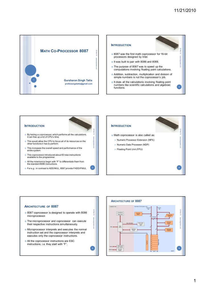
ARCHITECTURE OF 8087
8087 coprocessor is designed to operate with 8086
microprocessor.
The microprocessor and coprocessor can execute
their respective instructions simultaneously.
Microprocessor interprets and executes the normal
instruction set and the coprocessor interprets and executes only the coprocessor instructions.
All the coprocessor instructions are ESC
instructions, i.e. they start with “F”.
20-Nov-10
5
www.eazynotes.com
ARCHITECTURE OF 8087
20-Nov-10
6
www.eazynotes.com