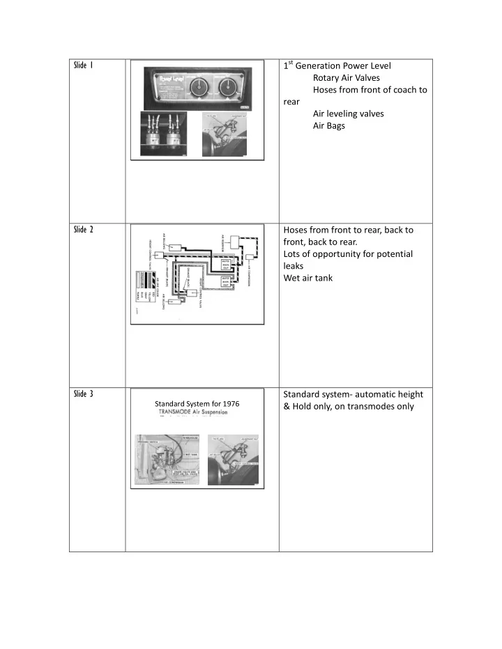
1 st Generation Power Level Rotary Air Valves Hoses from front of - - PDF document

1 st generation power level rotary air valves hoses from
SMART_READER_LITE
LIVE PREVIEW

1 st Generation Power Level Rotary Air Valves Hoses from front of - - PDF document

1 st Generation Power Level Rotary Air Valves Hoses from front of coach to rear Air leveling valves Air Bags Hoses from front to rear, back to front, back to rear. Lots of


slide-1
SLIDE 1
  • 1st Generation Power Level

Rotary Air Valves Hoses from front of coach to rear Air leveling valves Air Bags

  • Hoses from front to rear, back to

front, back to rear. Lots of opportunity for potential leaks Wet air tank

  • Standard System for 1976
  • Standard system- automatic height

& Hold only, on transmodes only

slide-2
SLIDE 2
  • Automatic and hold only. No

leveling capability. Wet Air Tank

  • Electro Level

Electric switches for control panel 6 solenoid valves Compressor and Wet Air Tank leveling valves Eliminated the rotary valves

  • Compressor & All air hoses at the

rear

slide-3
SLIDE 3
  • Wiring Diagram- 7 wires required

from control panel to compressor & 6 valves in the rear.

  • Electro Level II

Same switch control panel as Electro Level but wired differently Parts used on other GM vehicles Electronic Height Sensors 2 compressors- separate systems for each side of the coach Air Dryers- dry air system with no wet tank

  • Air schematic of Electro Level II-

Minimal hoses from compressor to Air Bags Dry air system- dryer fills air bags with dry air. When air is bleed from system, the dry air dries the Dryer as it passes to the ‘Bleed Solenoid’ Clean system with no internal rust and corrosion Note the arrow direction on the ‘Hold Solenoids’. I found that my air bag on the right side was leaking

  • down. After much checking for

leaks, and checking Dave Murmert’s site I discovered that after 30 years the pressure was leaking though the

slide-4
SLIDE 4

‘Hold Solenoid’. I ordered a new valve and turned the old one around while waiting for the new

  • ne to be delivered. No more

leaking past the valve. So…. I am the proud owner of a new part that has never been installed.

  • In my opinion these arrow are

‘WRONG’. They should point toward the normal lowest pressure. The internal spring must keep the valve closed if mounted in this

  • rientation. Over the years they

tend to leak. If mounted the

  • pposite direction then the

pressure keeps the valve closed.

  • Electro Level II wiring diagram:

Solenoids are switched by the negative side of the circuit by both the switches and the electronic height sensors 6 wires required from switch panel to compressors Could probably rewire Electro Level to Electro Level II and eliminate air height valves.

slide-5
SLIDE 5
  • Electro level II

Sensors

  • A previous owner had removed all the leveling sensors, links, and wiring

from my 78 GMC with Electro Level II. I quickly tired of checking ride

  • height. While seeking replacement I realized that others who wanted to

retrofit to Electro Level II could use my method on their coaches. I found an abundance of 89-92 Cadillacs at the men's mall and the rest is history. Follow along on an easy way to install Electronic Height Sensors on a GMC Motorhome.

  • A previous owner had removed all

the leveling sensors, links, and wiring from my 78 GMC with ElectroLevel II. I quickly tired of checking ride height. While seeking replacement I realized that others who wanted to retrofit to ElectroLevel II could use my method

  • n their coaches. I found an

abundance of 89-92 Cadillacs at the men's mall and the rest is history. Follow along on an easy way to install Electronic Height Sensors on a GMC Motorhome.

  • Parts: 2- leveling sensors/complete with bracket, link, stud ball, harness plug from 89-92

Cadillac FWD Deville; 1- leveling wiring harness from 1978 Cadillac Coupe Deville

  • Parts: 2- leveling sensors/complete

with bracket, link, stud ball, harness plug from 89-92 Cadillac FWD Deville; 1- leveling wiring harness from 1978 Cadillac Coupe Deville Found on 78 to 92+ Cadillacs, premium Olds & Buick cars and some mini-vans ’89 was the newest model I found that had the round plug

slide-6
SLIDE 6
  • There are plenty of these at the men's mall. Get some switches, a couple of hold

valves and make you own ElectroLevel II. Then you can toss those air tanks, leveling valves, control valves, and miles of hose.

  • There are plenty of these at the

men's mall. Get some switches, a couple of hold valves and make you

  • wn ElectroLevel II. Then you can

toss those air tanks, leveling valves, control valves, and miles of hose. I found the dryers missing on many Cadillacs and Oldsmobiles. Every Buick still had the dryer. They must not have known that Buicks had these also. Lincolns also have air suspensions and I would think their parts may also be adapted to our system

  • Round plug- direct plug in for GMC Motorhome
  • Found on some 1989 and older

autos.

slide-7
SLIDE 7
  • Rectangular plug (later model)-

wires or plug must be adapted to GMC Motorhome

  • All Models 1990 up
  • Sensor Wiring
  • A- Ground (Black wire)
  • B- Output (Yellow wire) recommend for compressor- raise
  • C- Power (Orange/ Black stripe)
  • D- Power (Pink / Black stripe)
  • E- Output (White wire) recommend for Bleed valve- lower
  • F- Unknown (Dark Blue wire) no delay?
  • Wire colors seem to be consistent

Electronic circuit- DO NOT SHORT

  • r Reverse Polarity
  • I made this monitoring device with a

spare sensor plug, 194 lights and sockets, test leads and a 9.6V drill battery.

  • I made this monitoring device with

a spare sensor plug, 194 lights and sockets, test leads and a 9.6V drill battery. 9- 12V seems adequate to operate circuit Recommend running the + through a test light or bulb as a safety precaution to limit the current in case of wiring snafu (Ken Henderson)

slide-8
SLIDE 8
  • I knew from observing the orientation of the

lever when I removed the sensor from the car that the neutral position was about 6 O'clock with the bracket on the left. So I set the arm to an obvious clockwise orientation to check operation and determine the neutral position. I later found out that the sensor mirrors itself in the 12-3 & 6-9 quadrants as well as the 3-6 & 9-12 mirror each other.

  • I knew from observing the
  • rientation of the lever when I

removed the sensor from the car that the neutral position was about 6 O'clock with the bracket on the

  • left. So I set the arm to an obvious

clockwise orientation to check

  • peration and determine the

neutral position. I later found out that the sensor mirrors itself in the 12-3 & 6-9 quadrants as well as the 3-6 & 9-12 mirror each

  • ther.12,3,6,9

The same sensor can be used on either side because it will have the same switching if it is reversed and turned upside down. Or you can keep the same orientation and mount one on the front ‘boggie’ and mount the sensor on the other side of the coach on the rear ‘boggie’.

  • AVI movie showing switching
  • peration of sensor.

*From neutral if the arm moves counterclockwise the air bleed switch is activated after ~ 20 sec *Moved clockwise to neutral - switch goes off & will stay off until moved from the neutral position *Moved clockwise the air bleed switch is activated after ~ 20 sec it

  • nly stays on for 3 seconds & goes
  • ff. Immediately the compressor

switch is activated for ~ 5 min. and then goes off. If more time is needed then cycle the ‘Travel Switch’ or the ignition. This action could be to purge the

slide-9
SLIDE 9

dryer of moisture before the compressor starts and to only allow the compressor to operate for a max of 5 min at a time. I have found that 5 minutes is ample time to raise a fully deflated air bag. *Moved counter-clockwise to neutral - switch goes off & will stay

  • ff until moved from the neutral

position *The 12-3 quadrant repeats the ‘Bleed’ operation of the 6-9 quadrant *Likewise the 3-6 quadrant repeats the 9-12 quadrant of ‘Bleed’ for 3 sec and ‘Compressor’ for 5 min. *Moving from 6 to the 6-9 quadrant duplicates the first experience in this quadrant

  • These sensors have a 12" wire loom

that exits the sensor with a 2 x3 water tight connector on the end. The terminals are labeled 'A' - 'F'. I consulting manuals and Dave Mumert's site (www.mumert.com/el2000.htm) to identify the terminals. Since terminal 'F' coincided to a blank on the wiring harness I did not check its purpose. Using a power source- 'A' to ground through a test light to limit load, 'C' & 'D' to positive, 'B' to a yellow test light to positive for detection of load, and 'E' to a red test light to positive for a detection

  • f load. After a 20 sec. delay the

ground circuit was completed to terminal 'E'. You can use test lights as well to test the circuits

slide-10
SLIDE 10
  • Comes after slide 22 The lever was

moved counterclockwise from neutral and after a 20 second delay terminal ground switching was active on terminal 'E' for 2 seconds.

  • When the connection on terminal

'E' turned off, ground switching on terminal 'B' was active for 5

  • minutes. If the lever is then moved

to neutral or to a clockwise

  • rientation the sensor would reset

and again activate the appropriate circuit.

slide-11
SLIDE 11
  • The lever was moved

counterclockwise until the light went out and the sensor was marked. *Marked before sensor is installed

  • Supplies: 4 -1/4\" lag screws, 2-

fender washers, 2- 1/4 x 7 /16 T-nuts from Lowe\'s, 2- cable clips from Radio Shack

  • Slide comes after 25The circuit is

cancelled if the lever is moved to the neutral position.

slide-12
SLIDE 12
  • Square the bracket on sensor so

that it will mount in the appropriate position on the left side of the wheel well.

  • Use an appropriate drill bit and 1/4"

lag screw to secure the sensor to the wheel well.

slide-13
SLIDE 13
  • Mount the sensor in the center

recess of the wheel well. It should be as close to the top and back wall as possible so that it is out of the way and is not obstructed in movement.

  • Rethread the stud ball to 1/4 x 20

threads to match those on the 'T nut'.

  • The orientation of the stud balls on

the link can easily be done by using to wrenches on the flats of the ends to rotate them into position.

slide-14
SLIDE 14
  • The stud balls need to be orientated

in the same direction.

  • Drill out the mounting hole to 5/16".
  • Cut the barbs from the 'T nut' and

slip it into the mounting hole.

slide-15
SLIDE 15
  • Release the end clip from one end
  • f the link by prying the clip and

allow the stud ball to slip out of the retainer.

  • Use a die and cut threads on the

stud ball to match those on the 'T nut'. Screw the stud ball into the 'T nut'.

  • Stud ball mounted .
slide-16
SLIDE 16
  • With the link mounted, the sensor

lever end of the link tracks below the link end on the "suspension arm" through the "suspension arm's" travel arc. This does not allow the link to flip the sensor lever over to the top side of the suspension arm. If that was allowed to happen there would not be reliable sensor tracking.

  • Left sensor mounted.
  • I cut a height gage out of 2 x 6 (8

5/8" long). Place the gage in the proper location under the frame at the oval hole and carefully lower the coach to touch the gage.

slide-17
SLIDE 17
  • The proper setting is out of

adjustment range. So I used a large fender washer to clamp the sensor lever to the sensor shaft. * Could check with tester w/o having to try to monitor the compressor & Bleed solenoids

  • With the height gage in place and

using the monitoring device set the arm so that the sensor is in its neutral position (no lights lit). The marks should be lined up. The height adjustment is made and the screw secured to lock-in the setting.

  • *The Red tell-tale lights indicate

which compressor is being requested to run and raise the coach. *The yellow tell-tale lights indicate which bleed valve is being requested to exhale to lower the coach. *Ground wiring is readily available at the switch terminals.

slide-18
SLIDE 18
slide-19
SLIDE 19
  • Comes after slide 22 The lever was

moved counterclockwise from neutral and after a 20 second delay terminal ground switching was active on terminal 'E' for 2 seconds.

slide-20
SLIDE 20
  • Slide comes after 25The circuit is

cancelled if the lever is moved to the neutral position.