1
play

1 Twisted Pair Twisted Pair - Applications Most common medium - PDF document

William Stallings Overview Data and Computer Communications Guided - wire 7 th Edition Unguided - wireless Characteristics and quality determined by medium and signal Chapter 4 For guided, the medium is more important


  1. William Stallings Overview Data and Computer Communications • Guided - wire 7 th Edition • Unguided - wireless • Characteristics and quality determined by medium and signal Chapter 4 • For guided, the medium is more important Transmission Media • For unguided, the bandwidth produced by the antenna is more important • Key concerns are data rate and distance Design Factors Electromagnetic Spectrum • Bandwidth —Higher bandwidth gives higher data rate • Transmission impairments —Attenuation • Interference • Number of receivers —In guided media —More receivers (multi-point) introduce more attenuation
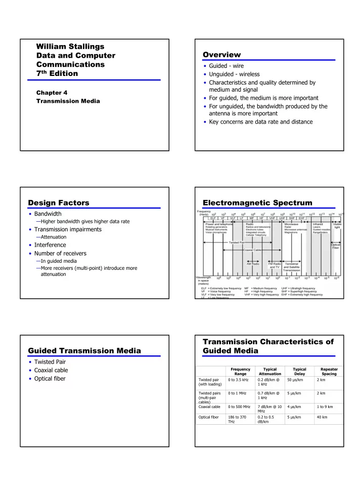
 Transmission Characteristics of Guided Transmission Media Guided Media • Twisted Pair • Coaxial cable Frequency Typical Typical Repeater Range Attenuation Delay Spacing • Optical fiber Twisted pair 0 to 3.5 kHz 0.2 dB/km @ 50 µs/km 2 km (with loading) 1 kHz Twisted pairs 0 to 1 MHz 0.7 dB/km @ 5 µs/km 2 km (multi-pair 1 kHz cables) Coaxial cable 0 to 500 MHz 7 dB/km @ 10 4 µs/km 1 to 9 km MHz Optical fiber 186 to 370 0.2 to 0.5 5 µs/km 40 km THz dB/km 1

  2. Twisted Pair Twisted Pair - Applications • Most common medium • Telephone network —Between house and local exchange (subscriber loop) • Within buildings —To private branch exchange (PBX) • For local area networks (LAN) —10Mbps or 100Mbps Twisted Pair - Transmission Twisted Pair - Pros and Cons Characteristics • Cheap • Analog • Easy to work with —Amplifiers every 5km to 6km • Digital • Low data rate —Use either analog or digital signals • Short range —repeater every 2km or 3km • Limited distance • Limited bandwidth (1MHz) • Limited data rate (100MHz) • Susceptible to interference and noise Near End Crosstalk Unshielded and Shielded TP • Coupling of signal from one pair to another • Unshielded Twisted Pair (UTP) • Coupling takes place when transmit signal —Ordinary telephone wire entering the link couples back to receiving pair —Cheapest —Easiest to install • i.e. near transmitted signal is picked up by near —Suffers from external EM interference receiving pair • Shielded Twisted Pair (STP) —Metal braid or sheathing that reduces interference —More expensive —Harder to handle (thick, heavy) 2

  3. Comparison of Shielded and UTP Categories Unshielded Twisted Pair Attenuation (dB per 100 m) Near-end Crosstalk (dB) • Cat 3 — up to 16MHz Frequency Category 3 Category 5 150-ohm Category 3 Category 5 150-ohm — Voice grade found in most offices (MHz) UTP UTP STP UTP UTP STP — Twist length of 7.5 cm to 10 cm • Cat 4 1 2.6 2.0 1.1 41 62 58 — up to 20 MHz • Cat 5 4 5.6 4.1 2.2 32 53 58 — up to 100MHz 16 13.1 8.2 4.4 23 44 50.4 — Commonly pre-installed in new office buildings — Twist length 0.6 cm to 0.85 cm 25 — 10.4 6.2 — 41 47.5 • Cat 5E (Enhanced) –see tables • Cat 6 100 — 22.0 12.3 — 32 38.5 • Cat 7 300 — — 21.4 — — 31.3 Twisted Pair Categories and Classes Coaxial Cable Category 3 Category 5 Category Category 6 Category 7 Class C Class D 5E Class E Class F Bandwidth 16 MHz 100 MHz 100 MHz 200 MHz 600 MHz Cable Type UTP UTP/FTP UTP/FTP UTP/FTP SSTP Link Cost 0.7 1 1.2 1.5 2.2 (Cat 5 =1) Coaxial Cable - Transmission Coaxial Cable Applications Characteristics • Most versatile medium • Analog • Television distribution —Amplifiers every few km —Closer if higher frequency —Ariel to TV —Up to 500MHz —Cable TV • Digital • Long distance telephone transmission —Repeater every 1km —Can carry 10,000 voice calls simultaneously —Closer for higher data rates —Being replaced by fiber optic • Short distance computer systems links • Local area networks 3

  4. Optical Fiber Optical Fiber - Benefits • Greater capacity —Data rates of hundreds of Gbps • Smaller size & weight • Lower attenuation • Electromagnetic isolation • Greater repeater spacing —10s of km at least Optical Fiber - Transmission Optical Fiber - Applications Characteristics • Act as wave guide for 10 14 to 10 15 Hz • Long-haul trunks • Metropolitan trunks —Portions of infrared and visible spectrum • Light Emitting Diode (LED) • Rural exchange trunks —Cheaper • Subscriber loops —Wider operating temp range • LANs —Last longer • Injection Laser Diode (ILD) —More efficient —Greater data rate • Wavelength Division Multiplexing Optical Fiber Transmission Frequency Utilization for Fiber Modes Applications Wavelength (in Frequency Band Fiber type Application vacuum) range range (THz) label (nm) 820 to 900 366 to 333 Multimode LAN 1280 to 1350 234 to 222 S Single mode Various 1528 to 1561 196 to 192 C Single mode WDM 1561 to 1620 185 to 192 L Single mode WDM 4

  5. Wireless Transmission Attenuation in Guided Media Frequencies • 2GHz to 40GHz —Microwave —Highly directional —Point to point —Satellite • 30MHz to 1GHz —Omnidirectional —Broadcast radio • 3 x 10 11 to 2 x 10 14 —Infrared —Local Antennas Radiation Pattern • Electrical conductor (or system of..) used to radiate • Power radiated in all directions electromagnetic energy or collect electromagnetic • Not same performance in all directions energy • Isotropic antenna is (theoretical) point in space • Transmission — Radio frequency energy from transmitter —Radiates in all directions equally — Converted to electromagnetic energy —Gives spherical radiation pattern — By antenna — Radiated into surrounding environment • Reception — Electromagnetic energy impinging on antenna — Converted to radio frequency electrical energy — Fed to receiver • Same antenna often used for both Parabolic Reflective Antenna Parabolic Reflective Antenna • Used for terrestrial and satellite microwave • Parabola is locus of point equidistant from a line and a point not on that line — Fixed point is focus — Line is directrix • Revolve parabola about axis to get paraboloid — Cross section parallel to axis gives parabola — Cross section perpendicular to axis gives circle • Source placed at focus will produce waves reflected from parabola in parallel to axis — Creates (theoretical) parallel beam of light/sound/radio • On reception, signal is concentrated at focus, where detector is placed 5

  6. Antenna Gain Terrestrial Microwave • Measure of directionality of antenna • Parabolic dish • Power output in particular direction compared • Focused beam with that produced by isotropic antenna • Line of sight • Measured in decibels (dB) • Long haul telecommunications • Results in loss in power in another direction • Higher frequencies give higher data rates • Effective area relates to size and shape —Related to gain Satellite Microwave Satellite Point to Point Link • Satellite is relay station • Satellite receives on one frequency, amplifies or repeats signal and transmits on another frequency • Requires geo-stationary orbit —Height of 35,784km • Television • Long distance telephone • Private business networks Satellite Broadcast Link Broadcast Radio • Omnidirectional • FM radio • UHF and VHF television • Line of sight • Suffers from multipath interference —Reflections 6

  7. Infrared Wireless Propagation • Modulate noncoherent infrared light • Signal travels along three routes — Ground wave • Line of sight (or reflection) • Follows contour of earth • Blocked by walls • Up to 2MHz • AM radio • e.g. TV remote control, IRD port — Sky wave • Amateur radio, BBC world service, Voice of America • Signal reflected from ionosphere layer of upper atmosphere • (Actually refracted) — Line of sight • Above 30Mhz • May be further than optical line of sight due to refraction • More later… Ground Wave Propagation Sky Wave Propagation Line of Sight Propagation Refraction • Velocity of electromagnetic wave is a function of density of material — ~3 x 10 8 m/s in vacuum, less in anything else • As wave moves from one medium to another, its speed changes — Causes bending of direction of wave at boundary — Towards more dense medium • Index of refraction (refractive index) is — Sin(angle of incidence)/sin(angle of refraction) — Varies with wavelength • May cause sudden change of direction at transition between media • May cause gradual bending if medium density is varying — Density of atmosphere decreases with height — Results in bending towards earth of radio waves 7

  8. Optical and Radio Horizons Line of Sight Transmission • Free space loss — Signal disperses with distance — Greater for lower frequencies (longer wavelengths) • Atmospheric Absorption — Water vapour and oxygen absorb radio signals — Water greatest at 22GHz, less below 15GHz — Oxygen greater at 60GHz, less below 30GHz — Rain and fog scatter radio waves • Multipath — Better to get line of sight if possible — Signal can be reflected causing multiple copies to be received — May be no direct signal at all — May reinforce or cancel direct signal • Refraction — May result in partial or total loss of signal at receiver Free Multipath Interference Space Loss Required Reading • Stallings Chapter 4 8

Download Presentation
Download Policy: The content available on the website is offered to you 'AS IS' for your personal information and use only. It cannot be commercialized, licensed, or distributed on other websites without prior consent from the author. To download a presentation, simply click this link. If you encounter any difficulties during the download process, it's possible that the publisher has removed the file from their server.

Recommend


More recommend