
1
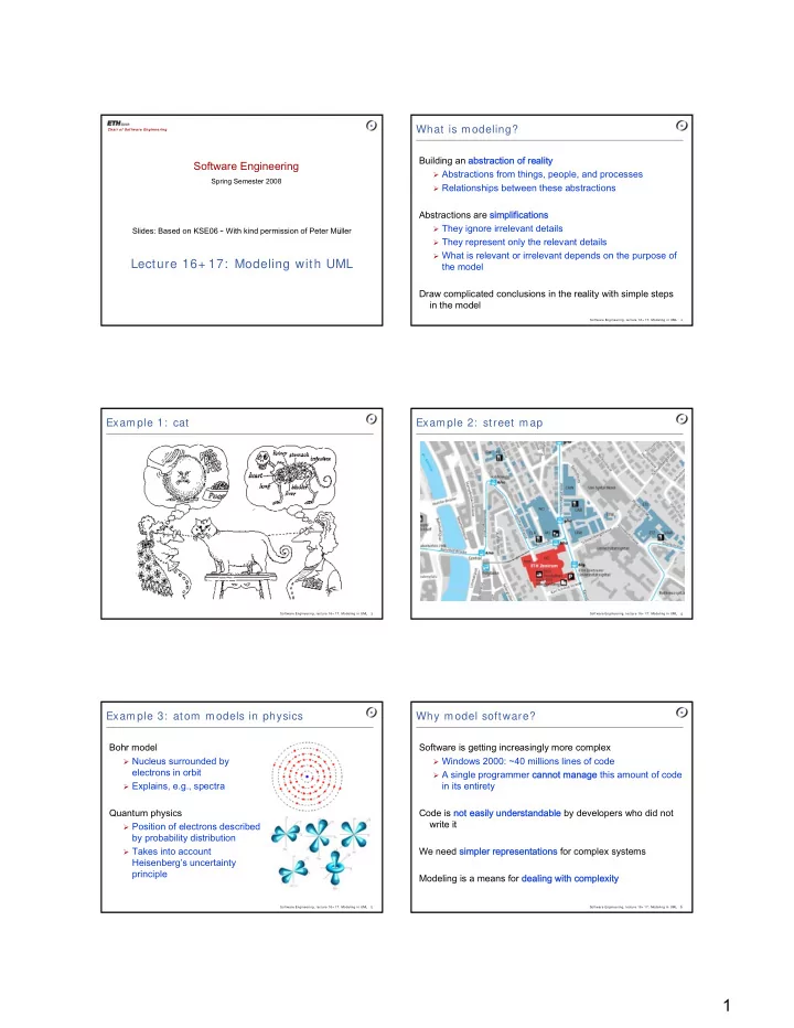
Software Engineering
Spring Semester 2008
Chair of Softw are Engineering
Lecture 16+ 17: Modeling with UML
Slides: Based on KSE06 – With kind permission of Peter Müller
Software Engineering, lecture 16+ 17: Modeling in UML 2
What is modeling?
Building an abstraction of reality
Abstractions from things, people, and processes Relationships between these abstractions
Abstractions are simplifications
They ignore irrelevant details They represent only the relevant details What is relevant or irrelevant depends on the purpose of
the model Draw complicated conclusions in the reality with simple steps in the model
Software Engineering, lecture 16+ 17: Modeling in UML 3
Example 1: cat
Software Engineering, lecture 16+ 17: Modeling in UML 4
Example 2: street map
Software Engineering, lecture 16+ 17: Modeling in UML 5
Example 3: atom models in physics
Bohr model
Nucleus surrounded by
electrons in orbit
Explains, e.g., spectra
Quantum physics
Position of electrons described
by probability distribution
Takes into account
Heisenberg’s uncertainty principle
Software Engineering, lecture 16+ 17: Modeling in UML 6
Why model software?
Software is getting increasingly more complex
Windows 2000: ~40 millions lines of code A single programmer cannot manage this amount of code