1 Load Word Kodas som 16 bitars jump offset fr att ange hur mnga - - PDF document

1
SMART_READER_LITE
LIVE PREVIEW

1 Load Word Kodas som 16 bitars jump offset fr att ange hur mnga - - PDF document

Fetch PC = PC+4 Execute Decode Digitalteknik och Datorarkitektur 5hp Single Cycle, Multicycle & Pipelining 7 maj 2008 karl.marklund@it.uu.se Single Cycle Datapath with Control Unit Hur ser det ut fr en instruktion av R-typ? P


slide-1
SLIDE 1

1

Digitalteknik och Datorarkitektur 5hp

Single Cycle, Multicycle & Pipelining

7 maj 2008

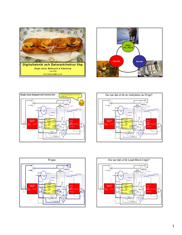
karl.marklund@it.uu.se Fetch PC = PC+4 Decode Execute Single Cycle Datapath with Control Unit

Read Address Instr[31-0] Instruction Memory Add PC 4 Write Data Read Addr 1 Read Addr 2 Write Addr Register File Read Data 1 Read Data 2 ALU

  • vf

zero

RegWrite Data Memory Address Write Data Read Data MemWrite MemRead Sign Extend 16 32 MemtoReg ALUSrc Shift left 2 Add PCSrc RegDst ALU control

1 1 1 1

ALUOp Instr[5-0] Instr[15-0] Instr[25-21] Instr[20-16] Instr[15

  • 11]

Control Unit Instr[31-26] Branch

På förra föreläsningen satt vi ihop allt det här..

Hur ser det ut för en instruktion av R-typ?

Read Address Instr[31-0] Instruction Memory Add PC 4 Write Data Read Addr 1 Read Addr 2 Write Addr Register File Read Data 1 Read Data 2 ALU

  • vf

zero

RegWrite Data Memory Address Write Data Read Data MemWrite MemRead Sign Extend 16 32 MemtoReg ALUSrc Shift left 2 Add PCSrc RegDst ALU control

1 1 1 1

ALUOp Instr[5-0] Instr[15-0] Instr[25-21] Instr[20-16] Instr[15

  • 11]

Control Unit Instr[31-26] Branch

R type

Read Address Instr[31-0] Instruction Memory Add PC 4 Write Data Read Addr 1 Read Addr 2 Write Addr Register File Read Data 1 Read Data 2 ALU

  • vf

zero

RegWrite Data Memory Address Write Data Read Data MemWrite MemRead Sign Extend 16 32 MemtoReg ALUSrc Shift left 2 Add PCSrc RegDst ALU control

1 1 1 1

ALUOp Instr[5-0] Instr[15-0] Instr[25-21]` Instr[20-16] Instr[15

  • 11]

Control Unit Instr[31-26] Branch

Hur ser det ut för Load Word (I-typ)?

Read Address Instr[31-0] Instruction Memory Add PC 4 Write Data Read Addr 1 Read Addr 2 Write Addr Register File Read Data 1 Read Data 2 ALU

  • vf

zero

RegWrite Data Memory Address Write Data Read Data MemWrite MemRead Sign Extend 16 32 MemtoReg ALUSrc Shift left 2 Add PCSrc RegDst ALU control

1 1 1 1

ALUOp Instr[5-0] Instr[15-0] Instr[25-21] Instr[20-16] Instr[15

  • 11]

Control Unit Instr[31-26] Branch

slide-2
SLIDE 2

2

Load Word

Read Address Instr[31-0] Instruction Memory Add PC 4 Write Data Read Addr 1 Read Addr 2 Write Addr Register File Read Data 1 Read Data 2 ALU

  • vf

zero

RegWrite Data Memory Address Write Data Read Data MemWrite MemRead Sign Extend 16 32 MemtoReg ALUSrc Shift left 2 Add PCSrc RegDst ALU control

1 1 1 1

ALUOp Instr[5-0] Instr[15-0] Instr[25-21]` Instr[20-16] Instr[15

  • 11]

Control Unit Instr[31-26] Branch

beq $t1, $t2 my_label

Hur funkar branch- instruktioner...

Kodas som 16 bitars jump offset för att ange hur många instruktioner vi skall hoppa (framåt eller bakåt)

Branch on Equal (beq)

Read Address Instr[31-0] Instruction Memory Add PC 4 Write Data Read Addr 1 Read Addr 2 Write Addr Register File Read Data 1 Read Data 2 ALU

  • vf

zero

RegWrite Data Memory Address Write Data Read Data MemWrite MemRead Sign Extend 16 32 MemtoReg ALUSrc Shift left 2 Add PCSrc RegDst ALU control

1 1 1 1

ALUOp Instr[5-0] Instr[15-0] Instr[25-21]` Instr[20-16] Instr[15

  • 11]

Control Unit Instr[31-26] Branch

På förra föreläsningen byggde vi en datapath i Logisim som klarade av add, addi och sub.

addi $t0, $zero, 127 addi $t1, $zero, 3 add $t2, $t0, $t1 add $t3, $t2, $t2 sub $t4, $t3, $t1

Begränsade oss till stöd för program liknande detta.

Single cycle design – fetch, decode and execute each instructions in one clock cycle

State element 1 State element 3 Combinational Logic 2 clock

  • ne clock cycle

No datapath resource can be used more than once per instruction, so some must be duplicated (e.g., separate Instruction Memory and Data Memory, several adders) Cycle time is determined by length of the longest path

Foto: C.E. Delohery some rights reserved

Fetch

PC = PC+4

Decode Execute

slide-3
SLIDE 3

3

Foto: Fort Photo some rights reserved

NOTE: this is a single-cycle implementation

Clock Cycle time must be long enough for the longest possible path

A god candidate for the longest path?

Load Word

Uses five functional units:

  • 1. Instruction memory
  • 2. Register file
  • 3. ALU
  • 4. Data memory
  • 5. Register file
  • 1. Instruction memory
  • 2. Register file
  • 3. ALU
  • 4. Register file

R-type instructions such as add etc only uses four functional units:

What about Store Word?

Single Cycle Disadvantages & Advantages

lw add

Waste

Cycle 2 Clk Cycle 1

Uses the clock cycle inefficiently – the clock cycle must be timed to accommodate the slowest instruction -- especially problematic for more complex instructions like floating point multiply. May be waste of area since some functional units (e.g., adders) must be duplicated since they can not be shared during a clock cycle Easy to understand and implement. We are on

  • ur way to

implement a single cycle datapath for MIPS in Logisim.

Multicycle Datapath Approach: let an instruction take

more than 1 clock cycle to complete. Break up instructions into steps where each step takes a cycle while trying to: Balance the amount of work to be done in each step. Restrict each cycle to use only one major functional unit.

In addition to faster clock rates, multicycle allows functional units that can be used more than once per instruction as long as they are used on different clock cycles, as a result only need one memory – but only one memory access per cycle need only one ALU/adder – but only one ALU operation per cycle

  • Not every

instruction takes the same number of clock cycles.

  • At the end of a cycle

– Store values needed in a later cycle by the current instruction in an internal register (not visible to the programmer). All (except IR) hold data only between a pair of adjacent clock cycles (no write control signal needed) – IR – Instruction Register MDR – Memory Data Register – A, B – regfile read data registers ALUout – ALU output register

Multicycle Datapath Approach

Address Read Data (Instr. or Data) Memory PC Write Data Read Addr 1 Read Addr 2 Write Addr Register File Read Data 1 Read Data 2 ALU Write Data IR MDR A B ALUout

– Data used by subsequent instructions are stored in programmer visible registers (i.e., register file, PC, or memory)

Not part of the ISA (Instruction Set Architecture) Parf of the ISA

The Multicycle Datapath

Address Read Data (Instr. or Data) Memory PC Write Data Read Addr 1 Read Addr 2 Write Addr Register File Read Data 1 Read Data 2 ALU Write Data IR MDR A B ALUout Sign Extend Shift left 2 Shift left 2 zero

1 1 1 1 1 1 2 2 3 4

Instr[5-0] Instr[25-0] Instr[15-0] 32 28

The Multicycle Datapath with Control Signals

Address Read Data (Instr. or Data) Memory PC Write Data Read Addr 1 Read Addr 2 Write Addr Register File Read Data 1 Read Data 2 ALU Write Data IR MDR A B ALUout Sign Extend Shift left 2

ALU control

Shift left 2

ALUOp

Control

IRWrite MemtoReg MemWrite MemRead IorD PCWrite PCWriteCond RegDst RegWrite ALUSrcA ALUSrcB

zero

PCSource

1 1 1 1 1 1 2 2 3 4

Instr[5-0] Instr[25-0] PC[31-28] Instr[15-0] Instr[31-26] 32 28

slide-4
SLIDE 4

4

The Five Steps of the Load Instruction

Cycle 1 Cycle 2 Cycle 3 Cycle 4 Cycle 5

lw

WB Mem Exec Dec IFetch

The Five Steps of the Load Instruction

Cycle 1 Cycle 2 Cycle 3 Cycle 4 Cycle 5

lw

WB Mem Exec Dec IFetch

  • IFetch: Instruction Fetch and Update PC

The Five Steps of the Load Instruction

Cycle 1 Cycle 2 Cycle 3 Cycle 4 Cycle 5

lw

WB Mem Exec Dec IFetch

  • IFetch: Instruction Fetch and Update PC
  • Dec: Instruction Decode, Register Read, Sign

Extend Offset

The Five Steps of the Load Instruction

Cycle 1 Cycle 2 Cycle 3 Cycle 4 Cycle 5

lw

WB Mem Exec Dec IFetch

  • IFetch: Instruction Fetch and Update PC
  • Dec: Instruction Decode, Register Read, Sign

Extend Offset

  • Exec: Execute R-type; Calculate Memory Address;

Branch Comparison; Branch and Jump Completion

  • Mem: Memory Read; Memory Write Completion; R-

type Completion (RegFile write)

  • WB: Memory Read Completion (RegFile write)

INSTRUCTIONS TAKE FROM 3 - 5 CYCLES!

slide-5
SLIDE 5

5

Review: Single Cycle vs. Multiple Cycle Timing

Clk Cycle 1

Multiple Cycle Implementation:

IFetch Dec Exec Mem WB Cycle 2 Cycle 3 Cycle 4 Cycle 5 Cycle 6 Cycle 7 Cycle 8 Cycle 9 Cycle 10 IFetch Dec Exec Mem

lw sw Clk Single Cycle Implementation: lw sw

Waste

Cycle 1 Cycle 2

multicycle clock slower than 1/5th

  • f single cycle clock due to stage

register overhead But for most instructions we are better off with multicycle.

Address Read Data (Instr. or Data) Memory PC Write Data Read Addr 1 Read Addr 2 Write Addr Register File Read Data 1 Read Data 2 ALU Write Data IR MDR A B ALUout

Cycle 1 IFetch Dec Exec Mem WB Cycle 2 Cycle 3 Cycle 4 Cycle 5 Cycle 6 Cycle 7 Cycle 8 Cycle 9 Cycle 10 IFetch Dec Exec Mem

lw sw

How can we make it even faster?

Split the multiple instruction cycle into smaller and smaller steps There is a point of diminishing returns where as much time is spent loading the state registers as doing the work. Fetch (and execute) more than

  • ne instruction at a time

Superscalar processing

CRAY-1 1976

Utilize Instruction-level parallelism within a single processor. Thereby allowing faster CPU throughput than would

  • therwise be possible at the same clock

rate.

1977

CRAY-1 1976

Veckans Macka!

Ein Belegtes Brot mit Schinken SCHINKEN! Ein Belegtes Brot mit Ei EI! Das sind Zwei belegte Brote, eins mit Schinken eins mit EI!

slide-6
SLIDE 6

6

Start fetching and executing the next instruction before the current one has completed.

CPUtime = IC x CPI x CC

Pipelining – (all?) modern rocessors are pipelined for performance

A Pipelined MIPS Processor

  • Start the next instruction before the current one has

completed

– improves throughput - total amount of work done in a given time – instruction latency (execution time, delay time, response time - time from the start of an instruction to its completion) is not reduced

Cycle 1 Cycle 2 Cycle 3 Cycle 4 Cycle 5

IFetch

lw

Cycle 7 Cycle 6 Cycle 8

sw

Dec IFetch

R-type

Exec Dec IFetch Mem Exec Dec WB Mem Exec WB Mem WB

  • clock cycle (pipeline stage time) is limited by the slowest

stage

for some instructions, some stages are wasted cycles

Single Cycle, Multiple Cycle, vs. Pipeline

Multiple Cycle Implementation: Clk

Cycle 1

IFetch Dec Exec Mem WB

Cycle 2 Cycle 3 Cycle 4 Cycle 5 Cycle 6 Cycle 7 Cycle 8 Cycle 9 Cycle 10

IFetch Dec Exec Mem lw sw IFetch R-type lw IFetch Dec Exec Mem WB Pipeline Implementation: IFetch Dec Exec Mem WB sw IFetch Dec Exec Mem WB R-type Clk Single Cycle Implementation: lw sw Waste Cycle 1 Cycle 2

Completing lw, sw and a R-type instruction takes

  • nly 7 cycles

MIPS Pipeline Datapath Modifications

  • What do we need to add/modify in our MIPS datapath?

– State registers between each pipeline stage to isolate them

Read Address

Instruction Memory

Add PC 4 Write Data Read Addr 1 Read Addr 2 Write Addr

Register File

Read Data 1 Read Data 2 16 32 ALU Shift left 2 Add

Data Memory

Address Write Data Read Data

IFetch/Dec Dec/Exec

Exec/Mem

Mem/WB

IF:IFetch ID:Dec EX:Execute MEM: MemAccess WB: WriteBack System Clock

Sign Extend

Foto: Land of the Lost some rights reserved

Pipelining the MIPS ISA Pipelining the MIPS ISA

Is it hard to introduce pipelining to MIPS?

EASY

  • all instructions are the same length

(32 bits)

  • can fetch in the 1st stage and

decode in the 2nd stage

  • few instruction formats (three) with

symmetry across formats

  • can begin reading register file

in 2nd stage

  • memory operations can occur only

in loads and stores

  • can use the execute stage to

calculate memory addresses

  • each MIPS instruction writes at

most one result (i.e., changes the machine state) and does so near the end of the pipeline (MEM and WB)

HARD

structural hazards:

what if we had only one memory?

control hazards: what

about branches?

data hazards: what if

an instruction’s input

  • perands depend on the
  • utput of a previous

instruction?

Graphically Representing MIPS Pipeline

  • Can help with answering questions like:

– How many cycles does it take to execute this code? – What is the ALU doing during cycle 4? – Is there a hazard, why does it occur, and how can it be fixed?

ALU IM Reg DM Reg

slide-7
SLIDE 7

7

Why Pipeline? For Performance!

I n s t r. O r d e r Time (clock cycles)

Inst 0 Inst 1 Inst 2 Inst 4 Inst 3

ALU IM Reg DM Reg ALU IM Reg DM Reg ALU IM Reg DM Reg ALU IM Reg DM Reg ALU IM Reg DM Reg

Time to fill the pipeline

Once the pipeline is full,

  • ne instruction

is completed every cycle, so CPI = 1 CPUtime = IC x CPI x CC

Can Pipelining Get Us Into Trouble?

  • Yes: Pipeline Hazards

– structural hazards: attempt to use the same resource by two different instructions at the same time – data hazards: attempt to use data before it is ready

  • An instruction’s source operand(s) are produced by a

prior instruction still in the pipeline – control hazards: attempt to make a decision about program control flow before the condition has been evaluated and the new PC target address calculated

  • branch instructions

Can always resolve hazards by waiting Pipeline control must detect the hazard and take action to resolve hazards I n s t r. O r d e r Time (clock cycles)

lw Inst 1 Inst 2 Inst 4 Inst 3

ALU Mem Reg Mem Reg ALU Mem Reg Mem Reg ALU Mem Reg Mem Reg ALU Mem Reg Mem Reg ALU Mem Reg Mem Reg

A Single Memory Would Be a Structural Hazard

Reading data from memory Reading instruction from memory

  • Fix with separate instr and data memories (I$ and D$)

How About Register File Access?

I n s t r. O r d e r Time (clock cycles)

Inst 1 Inst 2

ALU IM Reg DM Reg ALU IM Reg DM Reg ALU IM Reg DM Reg ALU IM Reg DM Reg

add $1, add $2,$1,

Fix register file access hazard by doing reads in the second half of the cycle and writes in the first half

Register Usage Can Cause Data Hazards

ALU IM Reg DM Reg ALU IM Reg DM Reg ALU IM Reg DM Reg ALU IM Reg DM Reg ALU IM Reg DM Reg

  • Dependencies backward in time cause hazards

add $1, sub $4,$1,$5 and $6,$1,$7 xor $4,$1,$5

  • r $8,$1,$9
  • Read before write data hazard

Loads Can Cause Data Hazards

I n s t r. O r d e r

lw $1,4($2) sub $4,$1,$5 and $6,$1,$7 xor $4,$1,$5

  • r $8,$1,$9

ALU IM Reg DM Reg ALU IM Reg DM Reg ALU IM Reg DM Reg ALU IM Reg DM Reg ALU IM Reg DM Reg

  • Dependencies backward in time cause hazards
  • Load-use data hazard
slide-8
SLIDE 8

8

stall stall

One Way to “Fix” a Data Hazard

I n s t r. O r d e r

add $1,

ALU IM Reg DM Reg

sub $4,$1,$5 and $6,$1,$7

ALU IM Reg DM Reg ALU IM Reg DM Reg

Can fix data hazard by waiting – stall – but impacts CPI

Another Way to “Fix” a Data Hazard

ALU IM Reg DM Reg ALU IM Reg DM Reg ALU IM Reg DM Reg ALU IM Reg DM Reg ALU IM Reg DM Reg

I n s t r. O r d e r

add $1, sub $4,$1,$5 and $6,$1,$7 xor $4,$1,$5

  • r $8,$1,$9

Fix data hazards by forwarding results as soon as they are available to where they are needed

Forwarding with Load-use Data Hazards

ALU IM Reg DM Reg ALU IM Reg DM Reg ALU IM Reg DM Reg ALU IM Reg DM Reg ALU IM Reg DM Reg

  • Will still need one stall cycle even with

forwarding

I n s t r. O r d e r

lw $1,4($2) sub $4,$1,$5 and $6,$1,$7 xor $4,$1,$5

  • r $8,$1,$9

Cannot forward backwards in time!

E n ” s m a r t ” k

  • m

p i l a t

  • r

k a n f l y t t a

  • m

i n s t r u k t i

  • n

e r f ö r a t t

  • m

m ö j l i g t u n d v i k a l

  • a

d

  • u

s e d a t a h a z a r d s . Branch Instructions Cause Control Hazards

I n s t r. O r d e r

lw Inst 4 Inst 3 beq

ALU IM Reg DM Reg ALU IM Reg DM Reg ALU IM Reg DM Reg ALU IM Reg DM Reg

  • Dependencies backward in time cause hazards

Don’t know the correct value of PC yet… stall stall stall

One Way to “Fix” a Control Hazard

I n s t r. O r d e r

beq

ALU IM Reg DM Reg

lw

ALU IM Reg DM Reg ALU

Inst 3

IM Reg DM

Fix branch hazard by waiting – stall – but affects CPI

slide-9
SLIDE 9

9

stall

Another Way to “Fix” a Control Hazard

I n s t r. O r d e r

beq

ALU IM Reg DM Reg

lw

ALU IM Reg DM Reg

Extra hardware to test registers and calculate branch address…

Branch Prediciton to “Fix” a Control Hazard

I n s t r. O r d e r

beq

ALU IM Reg DM Reg

lw

ALU IM Reg DM Reg

Predict all branches are not taken.

Branch Prediciton to “Fix” a Control Hazard

I n s t r. O r d e r

beq

ALU IM Reg DM Reg

addi

ALU IM Reg DM Reg

Extra hardware to test registers and calculate branch address. stall Only need to stall pipeline if branch is taken. Finns det inte något smartare sätt att ”gissa” ?

Dynamic Branch Prediction...

MIPS Pipeline Datapath Modifications

Read Address

Instruction Memory

Add PC 4 Write Data Read Addr 1 Read Addr 2 Write Addr

Register File

Read Data 1 Read Data 2 16 32 ALU Shift left 2 Add

Data Memory

Address Write Data Read Data

IFetch/Dec Dec/Exec

Exec/Mem

Mem/WB

IF:IFetch ID:Dec EX:Execute MEM: MemAccess WB: WriteBack System Clock

Sign Extend

Har vi glömt något?

Read Address

Instruction Memory

Add PC 4 Write Data Read Addr 1 Read Addr 2 Write Addr

Register File

Read Data 1 Read Data 2 16 32 ALU Shift left 2 Add

Data Memory

Address Write Data Read Data

IFetch/Dec Dec/Exec

Exec/Mem

Mem/WB

IF:IFetch ID:Dec EX:Execute MEM: MemAccess WB: WriteBack System Clock

Sign Extend

Need to preserve the destination register address in the pipeline state registers

slide-10
SLIDE 10

10

Read Address

Instruction Memory

Add PC 4 Write Data Read Addr 1 Read Addr 2 Write Addr

Register File

Read Data 1 Read Data 2 16 32 ALU Shift left 2 Add

Data Memory

Address Write Data Read Data

IFetch/Dec Dec/Exec

Exec/Mem

Mem/WB

IF:IFetch ID:Dec EX:Execute MEM: MemAccess WB: WriteBack System Clock

Sign Extend

All control signals can be determined during Decode and held in the state registers between pipeline stages

Control

Other Pipeline Structures Are Possible

  • What about the (slow) multiply operation?

– Make the clock twice as slow or … – let it take two cycles (since it doesn’t use the DM stage)

ALU IM Reg DM Reg MUL ALU IM Reg DM1 Reg DM2

  • What if the data memory access is twice as slow as the

instruction memory? – make the clock twice as slow or … – let data memory access take two cycles (and keep the same clock rate)

Summary

  • All modern processors use pipelining
  • Pipelining doesn’t help latency of single task, it helps

throughput of entire workload

  • Potential speedup: a CPI of 1 and fast a CC
  • Pipeline rate limited by slowest pipeline stage

– Unbalanced pipe stages makes for inefficiencies – The time to “fill” pipeline and time to “drain” it can impact speedup for deep pipelines and short code runs

  • Must detect and resolve hazards

– Stalling negatively affects CPI (makes CPI less than the ideal of 1)

”start up” ”wind down” ”bubbles”

Det var allt för i dag.