1 Two Pass Method Components of Phong Illumination Remember the - - PDF document

1
SMART_READER_LITE
LIVE PREVIEW

1 Two Pass Method Components of Phong Illumination Remember the - - PDF document

Assignments New due dates Checkpoint 7 / Code tonight Photon Mapping Drop code in mycourses drop box. Renderman Due Nov 8 th (new date) Server up and running. Images on Web site Code in mycourses drop box.


slide-1
SLIDE 1

1

Photon Mapping

Assignments

  • New due dates

– Checkpoint 7 / Code – tonight

  • Drop code in mycourses drop box.
  • Renderman

– Due Nov 8th (new date) – Server up and running. – Images on Web site – Code in mycourses drop box. – DID I SAY VALUABLE PRIZES!!!!

Projects

  • Approx 17 projects
  • Listing of projects now on Web
  • Presentation schedule

– Presentations (20 min max) – Last 3 classes (week 10 + finals week) – Sign up

  • Email me with 1st , 2nd , 3rd choices
  • First come first served.
  • Presentations all signed up!!!

Finals date

  • For last day of presentations
  • Friday, November 18th
  • 12:30pm – 2:30pm
  • 70-1445
  • Times on SCHEDULE

Logistics

  • Final Report

– Introduction – Approach Taken – Implementation Details – Results – Appendix/Code

  • Presentation

– 10-15 minutes

  • All project material due Friday, Nov 18th

– No late submission

  • else I can’t get your grades in!

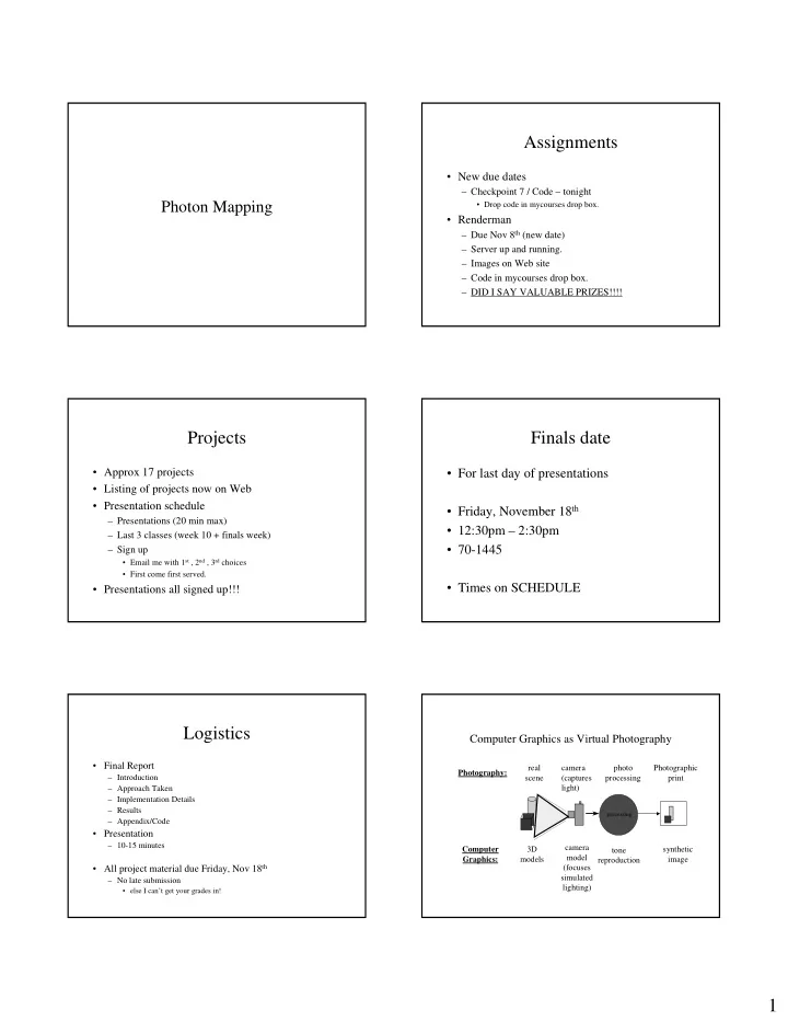
Computer Graphics as Virtual Photography

camera (captures light) synthetic image camera model (focuses simulated lighting)

processing

photo processing tone reproduction real scene 3D models Photography: Computer Graphics: Photographic print

slide-2
SLIDE 2

2 Two Pass Method

  • Remember the Phong Illumination Model
  • Most complete local illumination

approximation.

specular diffuse ambient

V) R ( N) S ( ) (

∑ ∑

  • +
  • +

=

i k i i s i i i d a a

e

L k L k L k V L

Components of Phong Illumination

  • Specular

– Dependent upon incoming and outgoing direction – Mirror-like reflection

  • Diffuse

– Assumes equal reflectance in all directions – BDRF is constant

Which Global Illumination Technique?

[Cohen85] [Heckbert84]

  • 1. Why a Two-Pass Global

Illumination Method?

  • Ray Tracing

– Good for specular reflections – Bad for diffuse reflections – View Dependent – Computationally intensive

  • Radiosity

– Good for diffuse reflections – Bad for specular reflections – View independent – Even more computationally intensive

  • A two-pass method gives us the best of both worlds

Two Pass Method

  • Pass 1: View independent (radiosity)
  • Pass 2: View dependent (ray tracing)

Two Pass Method

  • Four mechanisms of light transport between two

surfaces

Diffuse to Diffuse Specular to Diffuse Diffuse to Specular Specular to Specular BRDF (std radiosity) (std ray tracing)

[Wallace87]

slide-3
SLIDE 3

3 Two Pass Method - Preprocess

  • Pass 1: Use hemi-cube radiosity method

– View independent pass – Will provide diffuse reflections for all objects – Already handles diffuse-to-diffuse reflections – Basic algorithm is modified to account for

  • Diffuse reflections from specular sources
  • Diffuse transmission
  • Handles curved surfaces (Wallace)

(Sillion extended to all surface types)

Two Pass Method - Preprocess

  • Recall:

– Form factors give fraction of light emitted at

  • ne patch that arrive at another patch
  • Modification:

– Increase form factor for patch to account for additional light arriving at the point via specular reflection. – And transmission

Two Pass Method - Preprocess

  • Form Factor Modification

Like calculating reflection

[Wallace87]

Two Pass Method – Preprocessing Results For each surface, the diffuse intensity emitted by the surface has been calculated, whether light is received from diffuse or specular sources.

Two Pass Method - Pass Two

  • Pass 2: Ray Tracing

– View dependent pass – Calculation per pixel limits work – Ray tracing already accounts for specular-to- specular – Must be modified to accurately account for diffuse-to-specular

Two Pass Method - Pass Two Diffuse-to-specular

  • Ideally, would consider incoming light from all

directions that contribute to specular component.

  • In reality, the light contributing MOST HEAVILY to

specular reflection comes from direction of incident ray.

  • This allows limiting integration to solid angle over

which the weighted intensity is significant, rather than whole hemisphere.

slide-4
SLIDE 4

4 Two Pass Method - Pass Two The Reflection Frustum

  • Light is collected from a solid angle

surrounding the ray of incidence

  • The smaller angle, the more mirror-like

(material properties)

  • Solid angle is approximated by point samples
  • Light to be considered for specular reflection

is determined by a weighted average of the sampled rays

The Reflection Frustum

  • Sampling intensities arrive through reflection frustum
  • Incoming specularity is obtained recursively,

reducing resolution each level

[Wallace87]

The Reflection Frustum

  • Acts like integration with BDRF providing pre-

computed importance weights

  • Used a 10 x 10 pixel array
  • Used z-buffer
  • Diffuse component - Gouraud shading
  • Anti-aliasing performed by jittered rotation of

frustum

  • Solution similar to that used in distributed ray tracing

Two Pass Method

  • Reflection frustum - example

[Wallace87]

Two Pass Method - Example

Perfectly diffuse floors Floors after “polishing”

[Wallace87]

Two Pass Method - Summary

  • Rendering in Two Passes
  • Pass 1: Radiosity

– Considers diffuse-to-diffuse reflections – Considers specular-to-diffuse reflections

  • Pass 2: Ray Tracing

– Considers diffuse-to-specular reflections – Considers specular-to-specular reflections

  • The total light emitted at a point is

– Diffuse component, as calculated in Pass 1, plus – Specular component, as calculated in Pass 2

slide-5
SLIDE 5

5 Results

[Wallace87]

Results

[Wallace87]

Two Pass Method - Example

Without diffuse Diffuse to diffuse added Full solution

[Wallace87]

Ray Tracing

  • Integrated aspects of light and object

interaction that had formerly been handled by separate algorithms:

– Hidden surface removal – Reflection – Refraction – Shadows – Global specular interaction

Turner Whitted

Ray Tracing - Problems

  • Object - ray intersection
  • Ray traced images are point sampled

– “Too sharp” (super real) – “wrong image” – Sharp shadows – Sharp Reflection/Refraction

  • Multiple reflections especially are too sharp

– Aliasing

  • Doesn’t handle major light transport functions

– Diffuse interaction – Scattering of light – Caustics

  • Computation time

Ray Tracing – Avoiding Ray Traced Look

  • Avoiding that “ray traced look” , i.e., handle

diffuse interaction

– Ray tracing is point sampling

  • 1 ray per pixel

– Assumes pixel is a single point – Assumes pin hole camera

  • 1 ray for transmission & reflection

– Assumes all reflection is specular – Assumes that BRDF for all incoming directions is single

  • ut going direction
slide-6
SLIDE 6

6

Ray Tracing – Avoiding Ray Traced Look

  • Problem

– Only considering single path of light to eye for each pixel. – Only considering rays in perfectly reflective and transmissive directions.

  • Some approaches

– Trace objects other than rays – Stochastic sampling

The Rendering Equation

  • Local vs Global Illumination Models

Local illumination - only considers direct component Global illumination - also considers other scattered component

… + + + + =

scattering 3rd 3 scattering 2nd 2 scattering 1st direct

) ( ) ( ) ( Rg g Rg g Rg g g I ε ε ε ε

Indirect lighting

  • The ambient kludge

– Used to approximate light in those latter term of the rendering equation expansion

Indirect Lighting

Classic ray tracing Using photon mapping

Photon Mapping

  • Combines “backward”/ “reverse” ray tracing with

stochastic ray tracing

  • Used to simulate the interaction of light with a

variety transparent substances (caustics)

– Glass – Water – Diffuse Inter-reflections between illuminated objects – Effects of particulate matter

  • Smoke
  • Water vapor

Photon Mapping - Motivation

Without With

slide-7
SLIDE 7

7 Photon Mapping

  • Henrik Wann Jensen 95/96
  • Simulates the transport of individual photons

emitted from light sources

  • Photons bounce off specular surfaces
  • Photons deposited on diffuse surfaces
  • Photons collected by ray tracing from eye
  • http://www.ypoart.com/

Photon Mapping

  • Pass 1 – Shoot and Store Photons

– photons are shot from the light into the scene. – Photons are allowed to interact with objects in the environment – Where photons fall are stored in a special data structure called a “photon map” – 1000s of photons not billions

  • Statistical approximation based on density

Photon Mapping

  • Shooting photons

point directional square general [Jensen 2002]

Photon Mapping

  • Photon Scattering

[Jensen 2002]

Photon Map

  • The photon
  • Placed in k-d tree for efficient access

Photon Mapping

  • Pass 2 – Gather illumination

– Use ray tracing – Direct illumination determined by ray tracing – Indirect illumination determined by stochastically sampling photon map

slide-8
SLIDE 8

8 Monte Carlo methods

  • Driven by chance / randomness
  • Rendering and Monte Carlo

– Multiple rays per pixel

  • See how many reach a light

– Multiple rays from light

  • See how many reach the eye

– Photon Mapping

  • Goes from both sides

Photon Mapping - Caustics

  • Pattern of light focused on a surface after having
  • riginal light path bent by intermediate surface.

[Jensen]

Caustics

Reflective caustics Refractive caustics Yves Poissant

Photon Mapping

  • Three separate photon maps

– Global – photon emitted toward all objects – Caustics – specular to diffuse interactions – Volume – for volumetric effects

Photon Mapping

caustic global

The Light of Mies van der Rohe

2000ET

slide-9
SLIDE 9

9 Photon Mapping in real time

  • video

Want to learn more? Summary

  • Fixing ray tracing

– Spawning complex structures (cones, cylinders, etc.) – Stochastic sampling (distributed ray tracing, monte carlo) – “backwards” ray tracing (Photon Mapping)

  • Break.