
SLIDE 1
1
snick snack
CPSC 121: Models of Computation 2016W2
Propositional Logic, Continued Steve Wolfman, based on notes by Patrice Belleville and others
1
This work is licensed under a Creative Commons Attribution 3.0 Unported License.
Outline
- Learning Goals
- Problems and Discussion
– Side note: numbers from Booleans
- Expressiveness of Propositional Logic
- Next Lecture Notes
2
Learning Goals: In-Class
By the end of this unit, you should be able to:
– Build combinational computational systems using propositional logic expressions and equivalent digital logic circuits that solve real problems, e.g., our 7- or 4-segment LED displays (using a “DNF” or any other successful approach).
3
Where We Are in The Big Stories
Theory How do we model computational systems? Now: learning the underpinnings of all our models (formal logical reasoning with Boolean values). Hardware How do we build devices to compute? Now: establishing
- ur baseline tool
(gates), briefly justifying these as baselines, and designing complex functions from gates.
4
Outline
- Learning Goals
- Problems and Discussion
– Side note: numbers from Booleans
- Expressiveness of Propositional Logic
- Next Lecture Notes
5
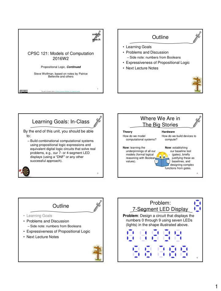
Problem: 7-Segment LED Display
Problem: Design a circuit that displays the numbers 0 through 9 using seven LEDs (lights) in the shape illustrated above.
6