
SLIDE 1
1
CS 640: Introduction to Computer Networks
Aditya Akella Lecture 7 - IP: Addressing and Forwarding
2
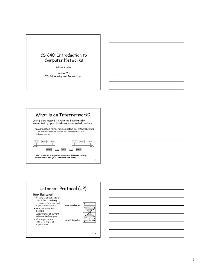
- Multiple incompatible LANs can be physically
connected by specialized computers called routers
- The connected networks are called an internetworks
– The Internet can be viewed as an internetwork of internetworks
host host host LAN 1 ... host host host LAN 2 ... router router router WAN WAN
LAN 1 and LAN 2 might be completely different, totally incompatible LANs (e.g., Ethernet and ATM)
What is an Internetwork?
3
Internet Protocol (IP)
- Hour Glass Model
– Create abstraction layer that hides underlying technology from network application software – Make as minimal as possible – Allows range of current & future technologies – Can support many different types of applications
Network technology Network applications
email WWW phone... SMTP HTTP RTP... TCP UDP… IP ethernet PPP… CSMA async sonet... copper fiber radio...