
Tamara Munzner http://www.ugrad.cs.ubc.ca/~cs314/Vjan2016
Viewing 3
University of British Columbia CPSC 314 Computer Graphics Jan-Apr 2016
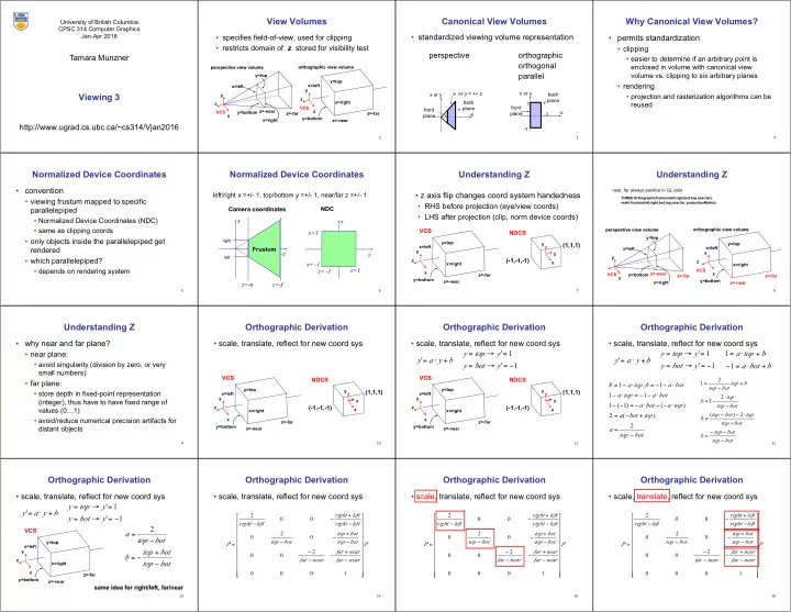
2View Volumes
- specifies field-of-view, used for clipping
- restricts domain of z stored for visibility test
z perspective view volume
- rthographic view volume
x=left x=right y=top y=bottom z=-near z=-far x VCS x z VCS y y x=left y=top x=right z=-far z=-near y=bottom
3Canonical View Volumes
- standardized viewing volume representation
perspective
- rthographic
- rthogonal
parallel
x or y
- z
1
- 1
- 1
front plane back plane x or y
- z
front plane back plane x or y = +/- z
4Why Canonical View Volumes?
- permits standardization
- clipping
- easier to determine if an arbitrary point is
enclosed in volume with canonical view volume vs. clipping to six arbitrary planes
- rendering
- projection and rasterization algorithms can be
reused
5Normalized Device Coordinates
- convention
- viewing frustum mapped to specific
parallelepiped
- Normalized Device Coordinates (NDC)
- same as clipping coords
- only objects inside the parallelepiped get
rendered
- which parallelepiped?
- depends on rendering system
Normalized Device Coordinates
left/right x =+/- 1, top/bottom y =+/- 1, near/far z =+/- 1
- z
x Frustum z=-n z=-f
right leftz x x= -1 z=1 x=1 Camera coordinates NDC z= -1
7Understanding Z
- z axis flip changes coord system handedness
- RHS before projection (eye/view coords)
- LHS after projection (clip, norm device coords)
x z
VCS
y x=left y=top x=right z=-far z=-near y=bottom x z
NDCS
y
(-1,-1,-1) (1,1,1)
8Understanding Z
near, far always positive in GL calls
THREE.OrthographicCamera(left,right,bot,top,near,far); mat4.frustum(left,right,bot,top,near,far, projectionMatrix);- rthographic view volume
x z VCS y x=left y=top x=right z=-far z=-near y=bottom perspective view volume x=left x=right y=top y=bottom z=-near z=-far x VCS y
9Understanding Z
- why near and far plane?
- near plane:
- avoid singularity (division by zero, or very
small numbers)
- far plane:
- store depth in fixed-point representation
(integer), thus have to have fixed range of values (0…1)
- avoid/reduce numerical precision artifacts for
distant objects
10Orthographic Derivation
- scale, translate, reflect for new coord sys
x z
VCS
y x=left y=top x=right z=-far z=-near y=bottom x z
NDCS
y
(-1,-1,-1) (1,1,1)
11Orthographic Derivation
- scale, translate, reflect for new coord sys
x z
VCS
y x=left y=top x=right z=-far z=-near y=bottom x z
NDCS
y
(-1,-1,-1) (1,1,1)
b y a y + ⋅ = ' 1 ' 1 ' − = → = = → = y bot y y top y
12Orthographic Derivation
- scale, translate, reflect for new coord sys
b y a y + ⋅ = ' 1 ' 1 ' − = → = = → = y bot y y top y
bot top bot top b bot top top bot top b bot top top b b top bot top − − − = − ⋅ − − = − ⋅ − = + − = 2 ) ( 2 1 2 1
b bot a b top a + ⋅ = − + ⋅ = 1 1
bot top a top bot a top a bot a bot a top a bot a b top a b − = + − = ⋅ − − ⋅ − = − − ⋅ − − = ⋅ − ⋅ − − = ⋅ − = 2 ) ( 2 ) ( ) 1 ( 1 1 1 1 , 1
13Orthographic Derivation
- scale, translate, reflect for new coord sys
x z
VCS
y x=left y=top x=right z=-far z=-near y=bottom
b y a y + ⋅ = ' 1 ' 1 ' − = → = = → = y bot y y top y bot top bot top b bot top a − + − = − = 2
same idea for right/left, far/near
14Orthographic Derivation
- scale, translate, reflect for new coord sys
P near far near far near far bot top bot top bot top left right left right left right P − + − − − − + − − − + − − = 1 2 2 2 '
15Orthographic Derivation
- scale, translate, reflect for new coord sys
P near far near far near far bot top bot top bot top left right left right left right P − + − − − − + − − − + − − = 1 2 2 2 '
16Orthographic Derivation
- scale, translate, reflect for new coord sys
P near far near far near far bot top bot top bot top left right left right left right P − + − − − − + − − − + − − = 1 2 2 2 '