
SLIDE 1
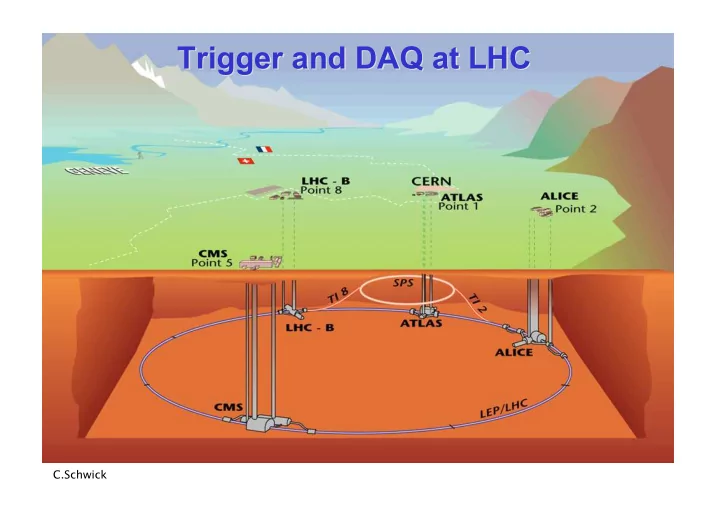
Trigger and DAQ at LHC Trigger and DAQ at LHC
C.Schwick
Trigger and DAQ at LHC Trigger and DAQ at LHC C.Schwick Contents - - PowerPoint PPT Presentation
Trigger and DAQ at LHC Trigger and DAQ at LHC C.Schwick Contents Contents INTRODUCTION The context: LHC & experiments PART1: Trigger at LHC Requirements & Concepts Muon and Calorimeter triggers (CMS and ATLAS) Specific solutions
C.Schwick
2
Requirements & Concepts Muon and Calorimeter triggers (CMS and ATLAS) Specific solutions (ALICE, LHCb) Hardware implementation
Data Flow of the 4 LHC experiments Data Readout (Interface to central DAQ systems) Event Building: CMS as an example Software: some technologies
3
Previous or current experiments
4
5
Trigger Rate (Hz) Size (Byte) Bandw.(GB/s) MB/s (Event/s)
LV-0 106
Pp-Pp500
p-p 103
High Level Trigger
6
Lvl-1 HLT Lvl-2 Data readout from Front End Electronics Temporary buffering
readout buffers Provide higher level trigger with partial event data Assemble events in single location and provide to High Level Trigger (HLT) Write selected events to permanent storage Lvl1 pipelines
custom hardware PC network switch
7
Lvl-1 HLT Lvl-2 Data readout from Front End Electronics Temporary buffering
readout buffers Provide higher level trigger with partial event data Assemble events in single location and provide to High Level Trigger (HLT) Write selected events to permanent storage Lvl1 pipelines
custom hardware PC network switch
8
9
10
Lvl-0,1,2
HLT
88µs lat custom hardware PC network switch readout link
11
Lvl-1 Lvl-2 HLT
3µs lat custom hardware PC network switch ROI Builder
Regions Of Interest Region Of Interest (ROI): Identified by Lvl1. Hint for Lvl2 to investigate further
readout link
12
Lvl-1 Lvl-2 HLT
4µs lat custom hardware PC network switch
readout link
13
Lvl-1 HLT
4µs lat custom hardware PC network switch readout link
14
Lvl-1 HLT
3µs lat custom hardware PC network switch readout link
15
16
17
no yes yes Yes Copper quad GbE Link ≈ 400 links Protocol: IPv4 (direct connection to GbE switch) Forms “Multi Event Fragments” Implements readout buffer
Optical 200 MB/s ≈ 500 links Half duplex: Controls FE (commands, Pedestals,Calibration data) Receiver card interfaces to PC
LVDS: 400 MB/s (max. 15m) ≈ 500 links (FE on average: 200 MB/s to readout buffer) Receiver card interfaces to commercial NIC (Network Interface Card)
Optical: 160 MB/s ≈ 1600 Links Receiver card interfaces to PC.
Flow Control
18
19
20
21
1kHz @ 1 MB = O(1) GB/s
hardware
22
Trigger Front End Readout Link Readout Buffer Event builder network Building Units High Level Trigger Farm (some 1000 CPUs) EVB Control
X X
23
24
25
26
27
28
29
30
all sources send to the same destination at (almost) concurrently. Congestion
31
32
33
34
35
36
37
38
39
40
41
42
43
44
45
46
47
48
49
50
51
52
53
Can be easily interfaced to FPGAs (custom electronics: receiving part of readout links)
54
% of wire-speed
55
56
57
58
Measurement 2003 (still valid)
59
60
61
62
Front End Readout Link Readout Buffer Event builder network Builder Units and High Level Trigger Farm
Trigger EVB Control: Event Manager
63
Trigger EVB Control: Event Manager
64
Trigger EVB Control: Event Manager
65
Trigger EVB Control: Event Manager
66
Trigger EVB Control: Event Manager
67
68
69
a “service”: find jets, find heavy particles, …)
classes which also contain the methods: – The class-designer is responsible for the data representation. – He can change it as long as the interface(= exposed functionality) stays the same.
70
71
72
73
74
Lvl-1 Lvl-2 HLT
Lvl-1 HLT
75
76
now
77
78
PCIexpress
79
X X Trigger Front End Readout Link Readout Buffer Event builder network Building Units High Level Trigger Farm EVB Control
80
Trigger Front End Readout Link Readout Buffer Event builder network Building Units High Level Trigger Farm EVB Control
81
Trigger,
Front End Readout Link Event builder network Building Units High Level Trigger Farm
Lvl1A & destination
82
Lvl-1 Lvl-2 HLT
Lvl-1 HLT
83
84
85
–150 –0.5 –300 –B-jets –132 –0.8 –165 –e * jet –170 –3.4 –50 –Jets, Jet * Miss-ET –390 –3.0 –130 –1τ, 2τ –2556 –3.6 –710 –1µ, 2µ –688 –4.3 –160 –1e/γ, 2e/γ –Total (s) –Rate (kHz) –CPU (ms)
–Trigger
86
87
88
89
90