The Piracy Threat Problem 1 : Unauthorized over production of IC - - PowerPoint PPT Presentation

the piracy threat
SMART_READER_LITE
LIVE PREVIEW

The Piracy Threat Problem 1 : Unauthorized over production of IC - - PowerPoint PPT Presentation

The Piracy Threat Problem 1 : Unauthorized over production of IC $$ Lost revenue opportunities Synthesis, Verification & Test for Secure ICs Undesired exposure of proprietary technology Protecting Integrated Circuits Problem


slide-1
SLIDE 1

Synthesis, Verification & Test for Secure ICs Protecting Integrated Circuits from Piracy with Test‐aware Logic Locking

Stephen Plaza Igor Markov
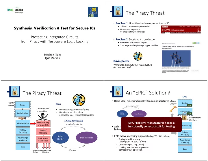
The Piracy Threat

  • Problem 1: Unauthorized over‐production of IC
  • $$ Lost revenue opportunities
  • Undesired exposure
  • f proprietary technology
  • Problem 2: Substandard production
  • Insertion of harmful Trojans
  • Sabotage and espionage opportunities

Driving factor

Worldwide distribution of IC production (i.e., outsourcing)

The Piracy Threat

Design Testing/ Packaging Advertising/ Marketing Sales Optimization Manufacturing

Rights holder

Manufacturing

  • f pirated ICs

Testing/ Packaging Black market distribution

Unauthorized production

Unauthorized Replica Unauthorized IC Variants

Rights Holder Manufacturer

IC design promised production

A Risky Relationship Risks

  • Manufacturing done by 3rd party
  • Manufacturing often done

in remote areas → fewer legal opons

An “EPIC” Solution?

  • Basic idea: hide functionality from manufacturer
  • Split manufacturing, test, etc

between different companies → infeasible

  • EPIC active metering approach [Roy ’08, ‘10 revision]
  • Springboard for many

subsequent research efforts

  • Unique chip ID (e.g., PUF)
  • Locking mechanism to prevent

correct circuit operation

Rights Holder Manufacturer non‐functional/incomplete IC design promised production

Design Optimization

Rights holder

PUF PUF Testing/ Packaging Advertising/ Marketing Sales Manufacturing unique unlocking key

EPIC Problem: Manufacturer needs a functionally correct circuit for testing

EPIC

insert random XOR logic

slide-2
SLIDE 2

Our Solution

Mux‐based locking that preserves test response → manufacturer does not activate the circuit Advantages

  • 1. Manufacturer never has

a functional circuit

  • 2. Supplied test response cannot

reveal locking scheme

  • 3. End‐user can validate authenticity

Design Optimization

Rights holder

PUF PUF Testing/ Packaging Advertising/ Marketing Sales Manufacturing

EPIC

Insertion of test‐preserving MUX locks

Outline

  • Background
  • XOR locking (and variants)
  • Types of attacks
  • XOR locking vulnerability to attacks
  • MUX‐based locking
  • Background on simulation‐based synthesis
  • Mux locking strategy
  • Practical considerations
  • Results

Circuit Locking

  • Add logic to the circuit to alter circuit output
  • Key bits that can disable locks

circuit CK1 CK2 CK3

Adding XOR‐based Locks

F

add lock

(XOR/XNOR)

hide key bit

(equivalent circuit) CKi XNOR XOR CKi F’ XOR

CKi

F

Properties

  • XORs placed randomly throughout circuit
  • Key bits not obvious even

with known output response key bit not obvious upon inspection

slide-3
SLIDE 3

Types of Attacks

  • Mask modification to disable PUF
  • Mask modification to disable locks
  • Hard to find on inspection
  • Hard to modify in current technologies
  • “Guess” key bit values
  • Random key patterns intractable
  • Simulation based on stolen netlist [Rajendran ’12]

(better placement of XORs make this attack difficult)

Supplied test patterns and response indicate expected behavior → potential attack vulnerability

Outline

  • Background
  • XOR locking (and variants)
  • Types of attacks
  • XOR locking vulnerability to attacks
  • MUX‐based locking
  • Background on simulation‐based synthesis
  • Mux locking strategy
  • Practical considerations
  • Results

XOR Lock Attack

High‐level Strategy

Assume access to key bits

  • Inputs: test pattern input, test pattern output, locked circuit
  • Output: key bit assignment that unlocks circuit

Algorithm

1. Choose a key bit at random 2. Apply all test patterns, observe test response 3. Flip key bit value 4. Apply all test patterns, observe test response 5. Choose the key bit value that minimizes test response differences 6. Repeat till convergence

XOR Lock Attack

circuit CK1 CK2 CK3

1

Pattern 1 Pattern 2

1 1 1 1 1

Response 1 Response 2

1 1

4 differences for CK1 = 1

… …

1

1 1

Response 1 Response 2

1 differences for CK1 = 0

slide-4
SLIDE 4

XOR Lock Attack Considerations

  • Output response often betrays gradient toward unlocked

configuration

  • Random restarts needed since algorithm gets caught in local

minimum

  • Adding XOR locks with downstream correlation can make a

naïve attack trickier

Outline

  • Background
  • XOR locking (and variants)
  • Types of attacks
  • XOR locking vulnerability to attacks
  • MUX‐based locking
  • Background on simulation‐based synthesis
  • Mux locking strategy
  • Practical considerations
  • Results

Efficient Resynthesis through Simulation‐based Approximations

  • Simulation can be used to approximate circuit behavior
  • Estimate average case behavior
  • Linear‐time computation
  • Apply values, e.g., random,

to primary inputs

  • Associate signatures

with each node

  • Use signatures to enable

complex optimizations

15

010 001 101 random simulation generate signatures

x x x x x x x x x

Signatures and Bit Simulation

  • Signature: partial truth table associated

with each node in a circuit

  • Stimulate inputs with simulation vectors

I 2 I 3 111 011 I 4 001 x2 I 1 011 011 001 x1 011 bit‐parallel simulation x3 010 x4 Sig(x1) = { 011}

slide-5
SLIDE 5

Signature‐based Synthesis Optimization

  • Use signatures to guide synthesis optimization
  • e.g., find signatures that are equal

and merge nodes

  • Need to prove equivalence (e.g., by using SAT)

circuit simplified

I 2 I 3 111 011 I 4 101 x2 I 1 100 011 001 x1 111 x3 001 x3 x4

010 010

f1 f2 sig(f1) = sig(f2) → merge? ,f1

Signature‐driven Locking Strategy

Apply Random Simulation Extract Signatures Find Equal Signature Verify Formally Optimize

equivalent

Node Merging with Signatures Finding Locks with Signatures Apply Test Patterns Extract Signatures Find Equal Signature Disprove with Random Simulation Add Lock

not equivalent repeat repeat

MUX

Finding Candidate Signatures

  • Problem: few signals with equal

signatures that are not logically equivalent

  • Solution: create equal signatures

using logic covers Logic Cover

  • ↔ &
  • ↔ |

Sigx2 SigX3 ↔ Sigx2 = Sigx3 & Sigx2

Synthesize x*2

x3 x2 x* 2

I 2 I 3 111 011 I 4 001 x2 I 1 100 011 001 x1 111 x3 101 x4

MUX‐based Locking Algorithm

  • 1. Apply Test Patterns

100

  • 2. Create Candidate Cover for

Randomly Chosen Node (most have covers)

x4 x3

011 010 010

= x3

x2 111 011 001 011 x1 111 x3 010 x4 x5

slide-6
SLIDE 6

MUX‐based Locking Algorithm

  • 3. Apply Random Simulation

011 111 101 x2 010 011 001 x1 011 x3 110 x4 x5 x2 x1 x4 x5

  • 5. Add MUX lock

key

x3

  • 4. Disprove Candidate Cover

x4 x3

011 110 010

≠ x3

Practical Considerations

  • f MUX Locking to the Design Flow

Area considerations

  • Each optimization requires minimal additional logic
  • Only a few locks (e.g. 64, 128) are needed for the key to be uncrackable

Timing and wiring

  • We avoid operations that increase logic levels
  • More generally: use local signals when synthesizing locks

to uphold ming/wiring constraints → need many candidate locking sites

Circuit Test…

2 gates

Problem 2: unpredictable output response could complicate diagnosing

Handling Untestable Logic with Probabilistic Testing

Problem 1: incorrect lock key will make some logic untestable

key = 1 (locked)

1

a not observable when b=0 b a key = 1 (locked)

1

b={1,0} a={0,0} c c={0,0} a={1,1} (stuck‐at‐1 fault) c={1,0}

expected faulty c = {1,1}

Handling Untestable Logic with Probabilistic Testing

Solution: run test patterns multiple times with different key bit values

Properties

  • If there are no interactions between locked sites, exponential

fewer untested sites for each combination

  • Improved testability possible because covers can increase
  • bservability of internal signals

circuit CK1 CK2 CK3

1

Pattern 1Pattern 2

1 1 1 1 1

Response 1 Response 2

1 1

… …

1

1 1

Response 1 Response 2

choose random combination

CK ={1,0,0}: Resp1, Resp2 CK ={1,0,1}: Resp1, Resp2 …. 1

slide-7
SLIDE 7

Yield‐aware Testing

Problem: test inputs change as a function of yield Solution: maintain large pool of test patterns compatible with locking

Design Derive test vectors Derive/Insert mux locks Rights holder Foundry

Design Under Test

Manufacture

Test Patterns

Yield Goals

Random test Random test Random test

Diagnosis choose subset

  • f test

patterns

Large Pool

  • f Test Patterns

Current Yield

Outline

  • Background
  • XOR locking (and variants)
  • Types of attacks
  • XOR locking vulnerability to attacks
  • MUX‐based locking
  • Background on simulation‐based synthesis
  • Mux locking strategy
  • Practical considerations
  • Results

Experimental Setup

  • Benchmark info
  • ISCAS89 and IWLS ‘05 benchmarks
  • Combinational portions considered

(latches treated as PIs and POs)

  • Circuits structurally hashed by ABC
  • All analysis at logic level (no place or route)

Circuit #Gates c880 383 usb_phy 1197 sasc 1651 c3540 1669 i2c 2902 pci_spoci_ctrl 3483 systemcdes 9008 spi 10109 tv80 22575 systemcaes 26717

Cracking XOR Locks

circuit #test patterns # Key Comb (64 bit) % circuits cracked #Key Comb (128 bit) % circuits cracked c880 53 ‐ ‐ usb_phy 67 37709 75 ‐ sasc 67 1334 100 174517 25 c3540 149 22624 100 ‐ i2c 164 11722 100 ‐ pci_spoci_ctrl 246 13196 100 ‐ systemcdes 123 4767 100 55005 50 spi 554 2290 100 131112 75 tv89 878 1727 75 ‐ systemcaes 426 2247 100 489 50 Smaller designs have more interactions between locks→ harder to crack Larger circuits like spi easily cracked even with 128 keys

  • 4 versions of each circuit with different locking configurations
  • Timeout: 1,000,000 combinations
slide-8
SLIDE 8

Adding MUX Locks

circuit % area overhead % signals with cover candidates lock insertion runtime (s) c880 33.4 67.4 1.8 usb_phy 10.7 54.0 1.0 sasc 7.8 57.4 0.2 c3540 7.6 58.4 116.9 i2c 4.4 53.0 4.7 pci_spoci_ctrl 3.7 73.4 12.3 systemcdes 1.4 67.0 6.9 spi 1.2 82.6 499.2 tv89 0.6 85.5 506.1 systemcaes 0.5 34.3 32.8

Small area overhead, fixed cost independent

  • f circuit size

Most signals have cover candidates (insertion is effectively random) Simulation dominates runtime: function

  • f circuit size and
  • bservability of signals
  • Inserts 64 locks for each circuit

Test Coverage

circuit % fault coverage (unlocked) % fault coverage (locked) c880 100 99.6 usb_phy 95.3 95.3 sasc 98.7 98.5 c3540 96.9 96.8 i2c 96.9 96.8 pci_spoci_ctrl 87.8 88.0 systemcdes 95.0 95.0 spi 91.1 91.2 tv89 90.8 90.8 systemcaes 91.9 91.9

Only one random assignment

  • f key bits still

leads to high test coverage It is possible that testing coverage is higher after adding MUX locks

diagnosability not significantly impacted

Conclusions

  • Demonstrated vulnerabilities to random XOR locking

simply using test patterns and simulation

  • Introduced a test‐aware circuit locking strategy that removes

the manufacturer from the chip activation loop (customer and rights owner can directly interact)

  • Demonstrated the scalable identification and injection of MUX

locks with minimal impact on area and timing

  • Showed negligible impact to circuit testability and diagnosability

Questions?

Stephen M. Plaza, Igor L. Markov: Solving the Third‐Shift Problem in IC Piracy With Test‐Aware Logic Locking. IEEE Trans. on CAD of Integrated Circuits and Systems 34(6): 961‐971 (2015)