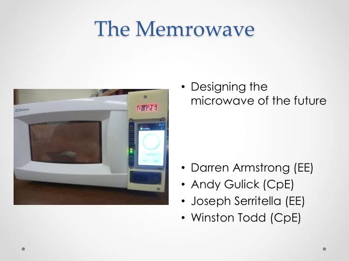
SLIDE 1 The Memrowave
microwave of the future
- Darren Armstrong (EE)
- Andy Gulick (CpE)
- Joseph Serritella (EE)
- Winston Todd (CpE)
SLIDE 2 Project Goals and Requirements
- The Goal of the project was to analyze the possible
design solutions to create
- Automated Microwave
- Using Barcode scanning
- WiFi connectivity
- Design a microwave that has
- An automatic timer and 10 power levels
- Local and online database
- Touch screen interfacing
SLIDE 3 Microwave specifications
- Developing a system that
- Scans barcodes within an average of 5 seconds
- Minimum storage capability for 1000 products
- Cycle through 10 power levels
- Power DC components with a maximum of 2
Amps
- Utilize 2.4 GHz Wi-Fi connections
SLIDE 4
Hardware Requirements
Requirement Constraint Resolution LCD 480X272 Camera Frame Rate 24 Frames per second LCD screen size 4.3” GPIO pins on microcontroller 4 pins Communication I2C Storage size 512MB Max power consumption 1070W
SLIDE 5
Hardware Selections
Selecting components to interface with microwave’s subsystems
SLIDE 6 User Interface/Control
Black Rev C
Cortex-A8
- 1 GHz
- 512MB DRAM
- Android 4.2.2 Jelly Bean
- Linux Kernel 3.2
- 5V, 460mA
- GPIO, I2C
SLIDE 7 LCD Touchscreen
- 4D Systems 4DCAPE-43T
- 4.3” TFT LCD
- 480x272 resolution
(portrait)
- Resistive touch
- Powered with 5V
directly from BBB headers
SLIDE 8 USB Camera/Wifi
- Logitech HD C270
- Video capture up to
1280 x 720 pixels
3.0 megapixels
- Logic Supply UWN200
- MediaTek MT7601
(Ralink 7601) controller
- 2.4GHz, 802.11b/g/n
- 4” antenna
SLIDE 9 Microwave Control
MSP430G2553 microcontroller
- 16MHz
- 16KB flash
- 1.8 - 3.6V, 330µA/MHz
- 20-pin plastic dual in-
line package (PDIP)
SLIDE 10 7-Segment LED Display
MAX6958
MAX6958
- LED display controller
- 16-pin PDIP
- 3V to 5.5V
- I2C
- Lite-On LTD-4708JR (x2)
- 2-digit, 7-segment LED
modules
SLIDE 11 Inter-Integrated Circuit (I2C)
- Computer bus
- Serial communication
- Half duplex
- Multi-master
- Up to 1008 nodes
(10-bit addressing)
- Single-ended signal
- 0.1-5.0 Mbit/s
Clock Data Master BBB Slave MSP430 Slave MAX
SLIDE 12 Microwave Control
BBB Header 7-segment display MSP430 Magnetron
MAX6958
Door Switch Piezo Speaker Fan Turntable Light I2C
SLIDE 13 Boards
START
PCB LCD BBB WiFi Camera
Not intended to be to scale
SLIDE 14
MSP430G2553
Control of Memrowave cook systems
SLIDE 15 MSP430G2553
- User safety
- Operate only at commanded power level
- Stop operation when door is opened
- Stop cooking within a maximum of 1 second if
Beaglebone Black is unresponsive
- Operation
- 5 sec minimum magnetron on-time
- Minimum magnetron off-time for power transitions
- < 100ms command execution response time
- Actual response time achieved: < 15ms
SLIDE 16
Cooking Cycle
5 10 15 20 25 1 2 3 4 5 6 7 8 9 10 Seconds Power Level Magnetron On Magnetron Off
SLIDE 17 Power Level Transition
Power Level Decrease Power Level Increase
On active level command Off On new level command Off full cook cycle is recalculated from this point Magnetron On active level command Off On new level command Off On idle time recalculated/ shifted according to the new commanded level Off Magnetron
SLIDE 18
Web Database
Internet accessible products database
SLIDE 19 Web Database
- A web database of products was implemented so
users will not have to manually enter product information
- Product settings can be cached to the
Memrowave’s local database
- MongoDB was used for the database
- Node.js + Express for the web server
- REST API will deliver JSON-formatted data
SLIDE 20
Web Database Schema
product( { name: String, description: String, upc: { type: String, index: true }, image_url: String, steps: [ ( { step_number: Number, instructions: String, cook_time: Number, power_level: Number, pause_before_step: Boolean } ) ] } )
SLIDE 21 Web Database
HTML Output JSON-formatted Data
SLIDE 22
Application Software
User interface and control of Memrowave systems
SLIDE 23 Home Screen
- Main entry point
- Five options
- Scan a barcode
- Manual Operation
- Favorites
- Timer
- Settings
SLIDE 24 Barcode Scanner
- Using the Zbar library to
decode barcodes
screen automatically scan and decode
scan success
search for matching products
SLIDE 25 Product Database
is used to store product information, including:
- Product name
- Product description
- Location of product
image
- Cooking steps, with
- Step instructions
- Power level
- Cook time
SLIDE 26 Product Search
matching barcode
- Search locations:
- Local database
- Web database
- Selecting a product will
bring up the Product Description screen, allowing the user to cook the product
SLIDE 27 Product Description
successful barcode scan, if a matching product can be found
edit, or delete the product.
the first step of the cooking process
SLIDE 28 Favorites
is used to store a list of favorite products
frequently used products
a barcode
SLIDE 29 Manual Operation
convenient barcodes
complete control over microwave operation
manually set cook time like a standard microwave
SLIDE 30 Cook Screen
Memrowave is cooking
screen to continue cooking
where the user cannot stop the microwave
the 7-segment display
SLIDE 31 New Product
product entries
used to take a picture
scan the barcode
cook time and power level
local database
SLIDE 32 Timer
to count down without cooking
displayed on the 7- segment display
SLIDE 33
Powering Systems
Powering elements in the Memrowave
SLIDE 34 Structure
- DC Components
- Beagle Bone Black
- LCD Display
- WIFI Module
- Camera
- 7 Segment Display
- AC Components
- Internal Light
- Turntable Motor
- Cooling Fan
- Magnetron Transformer
SLIDE 35 AC Power
120 V
microwave’s original wiring layout
door switches and magnetron relay
SLIDE 36 DC Components
Component Operating Voltage Max Operating Current(mA) Power(W)
BeagleBone Black 5 500 2.5 LCD Display 5 250 1.25 WIFI Module 5 500 2.5 Camera 5 500 2.5 7 Segment Display 3.3 600 1.98 MSP430 3.3 500 1.65 Total Power 12.4
SLIDE 37 DC Power Supply
- Maximum of 15 watts of power delivery
- Switching Regulator Design
- Minimize use of microwave real estate
Switching Regulator Design
- Maximum current requirement of 3 A
- Allows for a more compact design
- More efficient, 80-95%
- Requires more components
- EMI filtering/RF Considerations
SLIDE 38 Schematic
ON Semiconductor- LM2576, 5V 3A $2.35/ea
SLIDE 39 Mounting
- All internal assembly
- Two PCBs
- Able to acquire proper operation without extra
shielding
SLIDE 40
Electrical Hardware
Microwave electrical components
SLIDE 41 Electrical Hardware
- Controlling microwave’s electronics
- The relays and switches used to control the
hardware
- Control the Magnetron
- Lights
- Fan
- Turntable
- Door safety
- Circuit Design
- Printed Circuit Board
SLIDE 42 Electronics
- The Memrowave made use of
- The original magnetron
- The Lights
- Fan
- Turntable
- Electrical systems added to the chassis
- The Control PCB
- A USB camera and USB antenna
- The beagle housed inside a 3D printed case.
SLIDE 43 Controlling AC elements
- The Memrowave has a familiar functionality to
standard microwaves
- Components are only used when needed
- Power distributed effectively
- Safe operation
- Make use of switches
- Reuse the mechanical switches for the ovens door
- Utilize relays to control power
- Relays are controlled via the MSP430 slave
SLIDE 44 Control system
- In order to switch the relays we will utilize an MSP430
microcontroller
- The MSP430 is the slave to the beaglebone master
- The MSP430 will be mounted to the PCB
- The GPIO pins will output an on and off signal
- The MSP430 output current my not be efficient when
- perating relays
- To guarantee optimal currents to the relays BJT
transistors are used
- Make use of Three GPIO pins
- Magnetron
- Fan/Light/Turntable
- Piezo Speaker
SLIDE 45 Door Switch
- The mechanical switch in the door was reused
- This switch protects a user from the magnetron
when the door is open
- Opening the door will pause the cycle
- The door switch in connected to the salve MSP430
using the fabricated PCB
- The MSP430 monitors the voltage on a GPIO
- When the door is open the voltage drops to zero
SLIDE 46 Relays
- The Memrowave’s
- peration uses a Solid
State Relay and a mechanical relay
components are switched using a 8Amp Solid State Relay made by Sharp
- These elements are:
- Light
- Fan
- Turntable
A B C D
- The MSP430’s GPIO pin is used
to apply a 3.3V potential to the transistor’s base, which biases 3.3V across pins C to D
- The AC signals are switched
using pins A and B
SLIDE 47 Magnetron Relay
transformer draws a 9Amp current
magnetron required a more robust relay
relay was mounted to the microwave power PCB solve this issue
between the PCB and LCD cape
A B C D
- The MSP430’s GPIO pin is used
to apply a 3.3V potential to the transistor’s base, which applies 20V across pins C to D
- The magnetron’s AC signal is
switched using pins A and B
SLIDE 48
Control PCB layout
SLIDE 49
Final PCB
SLIDE 50 Administration
Budget Progress Labor Distribution Challenges Milestones
SLIDE 51
Budget
ITEM Estimated Cost Actual Cost Beagle Bone Black $50 $50 Camera $40 $27.02 LCD Screen $100 $60 Microwave $250 $ 0 Power supply $10 $37.98 Microcontroller $11 $0 Relays and Misc. $10 $27 PCB fabrication $60 $36.55 WIFI $25 $14.99 Total $556 $268.53
SLIDE 52 Progress
10 20 30 40 50 60 70 80 90 100 Percent Complete Design Prototyping Research Software
SLIDE 53
Distribution
Power/ PCB mgt User interface/ App Control system/ PCB Software Winston X X Andy X X Darren X Joseph X
SLIDE 54 Challenges
- Initial implantation of I2C
- First time working with PCB designs
- Inexperience with eagle schematic
- Problems mounting new hardware in the
microwave’s chassis
- Integrating Wi-Fi and camera with Android
hardware abstraction layer
SLIDE 55 Milestones
- Creating the user interface in android
- Testing control circuits on bread board
- Implementing I2C communication
- Controlling the 7-segment display
- Implementing the web database
- Having the MSP430 control all the sub systems
- Created a function switching regulator on a bread
board
- Ordering and fabricating the control PCB and
power PCB
SLIDE 56
Questions
SLIDE 57
Demo