Superluminal Velocities in Causal Media Department of Electrical and - - PowerPoint PPT Presentation

superluminal velocities in causal media
SMART_READER_LITE
LIVE PREVIEW

Superluminal Velocities in Causal Media Department of Electrical and - - PowerPoint PPT Presentation

Superluminal Velocities in Causal Media Department of Electrical and Computer Engineering Department of Electrical and Computer Engineering University of Toronto University of Toronto Group velocity I. Introduction (background) exceeding c,


slide-1
SLIDE 1

Superluminal Velocities in Causal Media

  • Dr. Mohammad Mojahedi, University of Toronto (KITP Quantum Optics Miniprogram 7/11/02)

1

Department of Electrical and Computer Engineering University of Toronto

Mohammad Mojahedi (UofT) George Eleftheriades (UofT) Omar Siddiqui (UofT) Jonathan Woodley (UofT) Kevin Malloy (UNM) Raymond Chiao (UC Berkeley)

Department of Electrical and Computer Engineering University of Toronto

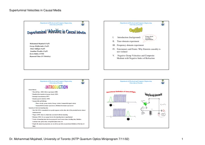
I. Introduction (background) II. Time-domain experiment

  • III. Frequency-domain experiment
  • IV. Forerunners and Fronts: Why Einstein causality is

not violated V. Negative Group Velocities and Composite Medium with Negative Index of Refraction

Group velocity exceeding c, (superluminal)

Department of Electrical and Computer Engineering University of Toronto

  • Early History

* Maxwell Eqs. (1865); Hertz experiment (1888) * Hamilton first mention of group velocity (1839) * Rayleigh Generalization (1877) * Einstein special relativity (1905) * Sommerfeld and Brillouin > Phase velocity, group velocity, Energy velocity, Sommerfeld signal velocity > Sommerfeld forerunner (precursor), Brillouin forerunner (precursor)

  • Question of electron tunneling time

* MacColl (1932): transmitted wave packet appears on the other side of the potential barrier almost instantaneously * Wigner (1955): there is a finite time associated with the tunneling * Hartman (1962): for an opaque barrier the tunneling time is superluminal * Variety of tunneling times has been proposed: local Larmor times, dwelling time, Buttiker- Landauer time, phase time, extrapolated phase time, etc. * Despite the numerous proposals, one can always provide an operational definition of the time-of- flight

Department of Electrical and Computer Engineering University of Toronto

Co inc . Co unt e r

*

UV Laser 1 DPC KDP Trombone Pris m

V

g ≈1.7 c

x 1 x = t1 x 2 x 2 = t2 x 1 x

slide-2
SLIDE 2

Superluminal Velocities in Causal Media

  • Dr. Mohammad Mojahedi, University of Toronto (KITP Quantum Optics Miniprogram 7/11/02)

2

Department of Electrical and Computer Engineering University of Toronto

  • Traditionally it was thought that tunneling wave packets were distorted such that it rendered the

group velocity meaningless or unphysical “When considerable absorption occurs. The group velocity can not be used, since in an absorbing medium wave packets are not propagated but rapidly ironed out” (Landau and Lifshitz, Electrodynamics of continuous media, pp. 285) “In particular, in regions of anomalous dispersion the group velocity may exceed the velocity of light or become negative, and in such cases it has no longer any appreciable physical significance” (Born and Wolf, Principles of optics, pp. 75) “…if absorption also occurs, a (the wave number) becomes complex or imaginary and the group velocity ceases to have a clear physical meaning” (Brillouin, Wave propagation in periodic structure, pp. 75)

  • J. D. Jackson had considered superluminal group velocity as “…just not a useful concept” (Classical

Electrodynamics, pp. 302), however this has been revised in 1998 edition.

Department of Electrical and Computer Engineering University of Toronto

TIME DOMAIN MEASUREMENTS

  • Single

microwave pulse 10 ns long (FWHM)

  • Centered at

9.68 GHz with 100 MHz bandwidth (FWHM)

"Side" "Center"

B W O M C C H A D e te c to r + A tte n u a to r F a s t T r ig g e r Cut Waveguide + Directional Coupler Rigid Coaxial cable SCD 5000 Tektronix SCD 5000 Tektronix

Department of Electrical and Computer Engineering University of Toronto

0.2 0.4 0.6 0.8 1 8 16 24 32 40 48 "side" "center" "side" raw data "center" raw data

Signal Amplitude [A.U.] Time [nano-second]

Average of five shots. Every third data point is shown. 0.6 0.7 0.8 0.9 1 1.1 15 16 17 18 19 20 21 22 "side" "center"

Signal Amplitude [A.U.] Time [nano-second]

Average of five shots

  • 1DPC with five

polycarbonate dielectric slab

  • The delay between

“center” and “side” is adjusted so the peaks arrive a at the same time

  • Solid curves are the

weighted-curve-fit (nonlinear least square fit)

Department of Electrical and Computer Engineering University of Toronto

0.6 0.7 0.8 0.9 1 1.1 15 16 17 18 19 20 21 22 "side" ; free-space "center" ; Tunneling

Signal Amplitude [A.U.] Time [ns]

Average of five shots 0.2 0.4 0.6 0.8 1 8 16 24 32 40 48 "side"; free-space "center"; Tunneling

Signal Amplitude [A.U.] Time [ns]

Average of five shots

  • The 1DPC is

inserted along “center” path

  • 440 ± 20 ps shift to

earlier times

  • Group velocity

(2.38 ± 0.15) c

440 ps

slide-3
SLIDE 3

Superluminal Velocities in Causal Media

  • Dr. Mohammad Mojahedi, University of Toronto (KITP Quantum Optics Miniprogram 7/11/02)

3

Department of Electrical and Computer Engineering University of Toronto Dispersion consideration

“… with anomalous dispersion, due to the strong absorption which destroys the significance of a characteristic wavelength after a short path, one can no longer sharply define the velocity of propagation of the energy” (L. Brillouin, Wave propagation and group velocity, pp. 22) “…but if absorption also occurs, a (the wave number) becomes complex or imaginary and the group velocity ceases to have a clear physical meaning” (L. Brillouin, Wave propagation in periodic structures, pp. 75)

0.2 0.4 0.6 0.8 1 8 16 24 32 40 48 "center" ; Tunneling "center" ; free-space

Signal Amplitude Time [nano-second]

Average of five shots Free space pulse is advanced in time

  • FWHM for free-space wave packet is 9.11 ns
  • FWHM for tunneling wave packet is 9.246 ns

1.5 % increase

Department of Electrical and Computer Engineering University of Toronto

V e c t o r N e tw o r k A n a ly z e r H P 8 7 2 2 D S H A S H A L e n s

  • 200
  • 150
  • 100
  • 50

50 100 150 200 0.0 0.2 0.4 0.6 0.8 1.0 20.0 20.5 21.0 21.5 22.0 22.5 23.0 Measured phase Calculated phase Measured amplitude Calculated amplitude Transmission Phase (Degree) Transmission amplitude Frequency (GHz)

Department of Electrical and Computer Engineering University of Toronto

ni = 1 nj = 3.4 − i 0.002 di = 1.76 cm dj =1.33 cm

ω φ τ ∂ ∂ − =

g

phase

  • n

transmissi ∴ φ

0.5 1 1.5 2 2.5 20 20.5 21 21.5 22 22.5 23

Group delay (ns) Frequency (GHz)

N = 4 3 2 1 Measurement Theory

  • 1200
  • 1000
  • 800
  • 600
  • 400
  • 200

20.0 20.5 21.0 21.5 22.0 22.5 23.0 Unwrapped Phase (Degree) Frequency (GHz) N =1 2 3 measurement Theory

Department of Electrical and Computer Engineering University of Toronto

Fitting, N = 3 N = 2 Fitting, N =1 Mea sured

di

1.794 cm 1.825 cm 1.76 cm

d j

1.399 cm 1.366 cm 1.396 cm 1.33 cm

′ n

j

3.216 3.288 3.245 3.40

′ ′ n

j

0.002 0.002 0.002 0.002

Best nonlinear least square fit based on Levenberg- Marquardt algorithm

V

g

Light Line

1 2 N =3 0.0 0.50 1.0 1.5 2.0 2.5 20.0 20.5 21.0 21.5 22.0 22.5 23.0

/c Frequency (GHz)

Fitted measurement Theory

Vg = LPC τg = LPC −∂φ ∂ω

( )

the physical thickness of the 1DPC

LPC :

slide-4
SLIDE 4

Superluminal Velocities in Causal Media

  • Dr. Mohammad Mojahedi, University of Toronto (KITP Quantum Optics Miniprogram 7/11/02)

4

Department of Electrical and Computer Engineering University of Toronto

  • The velocity of

the front (Sommerfeld forerunner) remains luminal under all circumstances

signal” velocity is to be associated with the velocity of the front

n (ω ω)

n = 1 x n = 1

x = 0 t

  • x = 0

t > 0

n (ω ω)

x

u x, t

( ) =

2 1 + n ω

( )

−∞ +∞

A ω

( ) e

i k ω

( ) x − i ω t dω

A ω

( )=

1 2 π u x = 0, t

( )

−∞ +∞

e

i ω t dt

  • For the pulse at normal incident
  • we require u(x,t) to have a well defined front, and the medium characterized by n(ω

ω) to be causal, i.e.,

u 0, t

( ) = 0

for t ≤ 0 u 0, t

( ) ≠ 0

for t > 0    G τ

( ) =

1 2 π ε ω

( ) ε 0 − 1

[ ]e

−i ω τ dω −∞ +∞

= 0 for t ≤ 0 and

u x, t

( ) = 0

for x − c t > 0 ≡ t0 > t ≡ v > c with t0 = x c & v = x t

is the susceptibility kernel

G τ

( )

Department of Electrical and Computer Engineering University of Toronto

  • u(x,t) is to be evaluated for t >

t0

  • For large frequencies
  • Since index of refraction is real the stationary phase condition can be used to obtain Sommerfeld Forerunner

frequency of oscillation

  • Solving Eq. (1) for
  • In Lorentzian medium , hence:
  • Eq. (2) can be solved for according to

ω = ωs n ω

( ) ≈1 −

′ G 0

( )

2 ω

2

n + ω d n ω

( )

d ω = 1 − ′ G 0

( )

2 ω

2 +ω

d d ω 1− ′ G 0

( )

2 ω

2

      = t t0 (1) ωs = ′ G 0

( )

2 t t0 − 1       , t0 = x c, (2) ωp

2 =

′ G 0

( )

ωs = ωp 2 t t0 − 1      

V = x t

V = x t = c 1 + ω p

2

2 ωs

2

( )

V → c as ω = ωs → ∞ G τ

( ) = 1

2 π ε ω

( ) ε0 − 1

[ ]e

−i ω τ dω −∞ +∞

Department of Electrical and Computer Engineering University of Toronto

  • Assume earliest part of a signal is modeled by
  • Using the above and the value of index for large frequencies,

can be evaluated with the help of contour integration in the LHP

  • As

sharper the input smaller the forerunner

  • For Lorentzian medium

u 0 , t

( ) =

a t m m ! ⇔ ℑ u 0 , t

( )

[ ] =

A ω

( ) =

a 2 π i ω    

m + 1

u x , t

( ) ≈ a

t − t0 γ     

m 2

J m 2 γ t − t0

( )

( ),

γ = ′ G

( )

2 c x = ′ G

( ) t 0

2 for t > t0 m ↑ ⇒ u x , t

( ) ↓ ⇒

u x, t

( )

′ G 0

( ) =ω p

2

m is an integer and a is a constant

Department of Electrical and Computer Engineering University of Toronto ( )

, sin sin 2 1 cos cos cos                       + −               = Λ c d n c d n n n n n c d n c d n K

j j i i i j j i j j i i

ω ω ω ω K Λ = ± cos

−1 h ni, nj, di, dj, υ

( )

[ ]+ 2 m π

with m = ...,−1, 0, 1, ...

Re ne

( ) =

′ n

e = c

ω Re K

( )

Im ne

( ) =

′ ′ n

e = c

ω Im K

( )

ne = ( ′ n

e) 2 + ( ′

′ n

e )2

[ ]

1/ 2 = c

ω K ni n j dj di

Λ

0.5 1 1.5 2 2.5 3 3.5 2 4 6 8 10 |n| N=1 |n| N=2 |n| N=4 |n| N=6 |n| N=8 Re(n) N=10 |n| N=

Frequency [GHz]

|ne|

slide-5
SLIDE 5

Superluminal Velocities in Causal Media

  • Dr. Mohammad Mojahedi, University of Toronto (KITP Quantum Optics Miniprogram 7/11/02)

5

Department of Electrical and Computer Engineering University of Toronto

Time (Pico-seconds)

  • Frequency of the forerunner decreases

with time

  • Amplitude of the forerunner increases

with time x = 100 µ m , λ 0 = 5 µ m ω p = 5 .38 × 10

15

Hz

S u p e rlu m in a l w a v e p a c k e t S o m m e rfe ld fo re ru n n e r B rillo u in f o re ru n n e r P u ls e e n v e lo p e

t=t0 Increasing Time

Department of Electrical and Computer Engineering University of Toronto

Meaning of Negative Group Velocity and Group Delay

  • For tunneling photons the group delay was positive,
  • In the case of negative group delay,

, the peak of the transmitted pulse leaves the medium prior to the peak of the incident pulse entering the medium

c L

g <

<τ > > = c L V

g g

τ <

g

τ <

g

V

V

g = c

ng = c n +ω dn dω

( )

1 − ≈ − = − = ∆

g g vac g

n c L c L V L t t τ

Vacuum Meta material L Medium with Negative GD

( ) ( ) ( )

t t f t f

e i

cosω =

( )

( ) ( )

p g e i

t t f t f τ ω ω τ cos − − = ( ) ( ) ( ) [ ]

ω φ ω ω exp T T =

( )

Velocity Group ; Delay Group ; Delay Phase ; Function Trans. ;

g g g p

L V T τ ω φ τ ω φ τ ω = ∂ ∂ − = = Department of Electrical and Computer Engineering University of Toronto

“ … and therefore when ε>0 and µ>0 the phase and group velocities have the same direction, but when ε<0 and µ<0 they have opposite direction.” V.G. Veselago Soviet Physics-Solid State Vol. 8. no. 12 “Since the vector K is in the direction of the phase velocity, it is clear that left- handed substances are substances with a so-called negative group velocity.” ( V.

  • G. Veselago Soviet Physics

USPEKHI Vol. 10. No. 4 “It should be noted that the possibility of the

  • pposite directions of ε and µ vectors is not
  • unusual. This is particularly the case in the

presence of spatial dispersion. Here, generally, one speaks of negative group velocity, though it would be more correct to speak of negative phase velocity, since the group velocity is always positive and is directed away from the radiation source to the receiver.” V. G. Veselago,

Negative Group Velocity in Meta Materials

Department of Electrical and Computer Engineering University of Toronto

  • 12
  • 10
  • 8
  • 6
  • 4
  • 2

18 20 22 24 26 28

Frequency (GHz) Transmission Magnitud

  • 100

100 200 300 400 500 600

  • Trans. Phase (Degree)
  • Trans. Mag.
  • Trans. Phase
  • 2.5
  • 2
  • 1.5
  • 1
  • 0.5

0.5 19 21 23 25

Fre quency (GHz) Re [n]

  • 4
  • 3
  • 2
  • 1

1

Norm alized Group V elocity

Re [n] Vg / c

Meta Material Slab Source Z

  • 2.5
  • 2
  • 1.5
  • 1
  • 0.5

0.5 18 20 22 24 26 Fre que ncy (G Hz) Re [n]

  • 3
  • 2.5
  • 2
  • 1.5
  • 1
  • 0.5

0.5 1 1.5 G roup Delay (ns) Re [n] Group Delay A B

slide-6
SLIDE 6

Superluminal Velocities in Causal Media

  • Dr. Mohammad Mojahedi, University of Toronto (KITP Quantum Optics Miniprogram 7/11/02)

6

Department of Electrical and Computer Engineering University of Toronto

  • 60
  • 50
  • 40
  • 30
  • 20
  • 10

4.5 5 5.5 6

Fre que ncy (GHz)

  • Trans. Mag. (dB)
  • 1000
  • 900
  • 800
  • 700
  • 600
  • 500
  • 400
  • 300
  • 200
  • 100

100

  • Trans. phase (Deg.)
  • Trans. Mag.
  • Trans. Phase
  • 1
  • 0.5

0.5 1 1.5 18 20 22 24 26 Fre que ncy (GHz) Group Delay (ns)

  • 100

100 200 300 400 500

  • Trans. Phase (Deg.)

Group Delay

  • Trans. Phase
  • 0.8
  • 0.6
  • 0.4
  • 0.2

0.2 0.4 18 20 22 24 26

Frequency (GHz) Group Delay (ns)

  • 50

50 100 150

  • Trans. Phase (Deg.)

Group Delay

  • Trans. Phase

Department of Electrical and Computer Engineering University of Toronto

  • 1
  • 0.8
  • 0.6
  • 0.4
  • 0.2

0.2 0.4 0.6 18 20 22 24 26

Freguency (GHz) Group Delay (ns)

  • 250
  • 200
  • 150
  • 100
  • 50

50 100 150

  • Trans. Phase (Deg.)

Group Delay

  • Trans. Phase
  • 2
  • 1.5
  • 1
  • 0.5

0.5 1 1.5 18 20 22 24 26

Frequency (GHz ) Group Delay (ns)

  • 40
  • 20

20 40 60 80 100 120

  • Trans. Phase (Deg.)

Group Delay

  • Trans. Phase
  • Structure has 7 SRR+ Wire Strips
  • Detuning was done by increasing

each unit cell size by 1%.

  • Physical thickness of the slab = Overall

thickness of SRR + Wire Strips

  • Detuning was done by introducing 7

resonances 1% apart in frequency.

Department of Electrical and Computer Engineering University of Toronto Co Lo Ro Cs Lsh

d/2 d/2

0.5 1 1.5 2 2.5 3 3.5

  • 4
  • 2

2 4

βd per unit cell (radians) Frequency (GHz)

–– Ro=150Ω –– Ro=300Ω f1 f2 f3

f<f1: First Stop Band f1<f<f2: First Pass Band f2 <f< f3 : Second Stop Band f> f3: Second Pass Band

  • 2
  • 1.5
  • 1
  • 0.5

1 1.2 1.4 1.6 1.8 2

Frequency (GHz) n

Unit Cell of the periodically loaded Transmission Line

Department of Electrical and Computer Engineering University of Toronto

0.5 1 1.5 2 2.5 x 10

−7

0.1 0.2 0.3 0.4 0.5 0.6 0.7 0.8 0.9 1

0.5 1 1.5 2 2.5 x 10 −7 0.1 0.2 0.3 0.4 0.5 0.6 0.7 0.8 0.9 1

Time in seconds Amplitude [A.U.] Vi Vo

  • 4
  • 2

2 4 1 1.2 1.4 1.6 1.8 2

Frequency (GHz) Group Delay (ns)

  4 Stages   3 Stages   2 Stages   1 Stages

  • 4
  • 2

2 4 0.5 1.5 2.5 3.5

Frequency (GHz) S21 Phase (Radians)

4 Stages 3 Stages 2 Stages 1 Stage f1 f2 f3

  • 30
  • 25
  • 20
  • 15
  • 10
  • 5

0.5 1.5 2.5 3.5

Frequency (GHz) S21 Magnitude (dB) 4 Stages 3 Stages 2 Stages 1 Stage

f1 f2 f3

slide-7
SLIDE 7

Superluminal Velocities in Causal Media

  • Dr. Mohammad Mojahedi, University of Toronto (KITP Quantum Optics Miniprogram 7/11/02)

7

Department of Electrical and Computer Engineering University of Toronto

GHz GHz GHz 0189 . 1 0000 . 1 9809 . = + = = − ω ω ω Distance [m]

  • 1.0
  • 0.5

0.0 0.5 1.0

  • 1.5 -1.0 -0.5

0.0 0.5 1.0 1.5 2.0 2.5 3.0 3.5 4.0

Region (1) Region (2) Region (3)

Peak In Region (1) Peak In Region (2) Peak In Region (2)

Region (1) Normal Material Region (2) Meta Material Region (3) Normal Material

Region (1)

ω

ωο ω+ ω-

ko k

Region (2)

ω

ωο ω+ ω-

  • k′o

k′

n=1 n=-1.73

Region (3)

ω

ωο ω+ ω- ko

k

n=1 Department of Electrical and Computer Engineering University of Toronto

Movie

Department of Electrical and Computer Engineering University of Toronto

  • It is shown that for a microwave pulse tuned to the mid-gap of a

photonic crystal, group velocity describes the propagation of the pulse envelop and is superluminal.

  • In a medium with negative group delay (negative group velocity) the

transmitted pulse leaves the medium prior to the peak (envelope) of the incident pulse entering the medium.

  • We have shown that medium with negative index of refraction

supports both positive and negative group delays (group velocities).

  • It is possible to use negative group delay to “practically” address the

issue of signal latency (propagation delay).

  • A mechanism to increase the negative group delay bandwidth is

proposed.

  • A periodically loaded transmission line exhibiting an equivalent

negative index of refraction and displaying negative group delay is proposed and results experimentally have been verified.

  • Under no circumstances the requirements of Einstein causality is

violated since the “front” always remains luminal.