SCOTT RIT-PAC III Objectives Describe the SCOTT RIT-PAC III and - - PDF document

scott rit pac iii
SMART_READER_LITE
LIVE PREVIEW

SCOTT RIT-PAC III Objectives Describe the SCOTT RIT-PAC III and - - PDF document

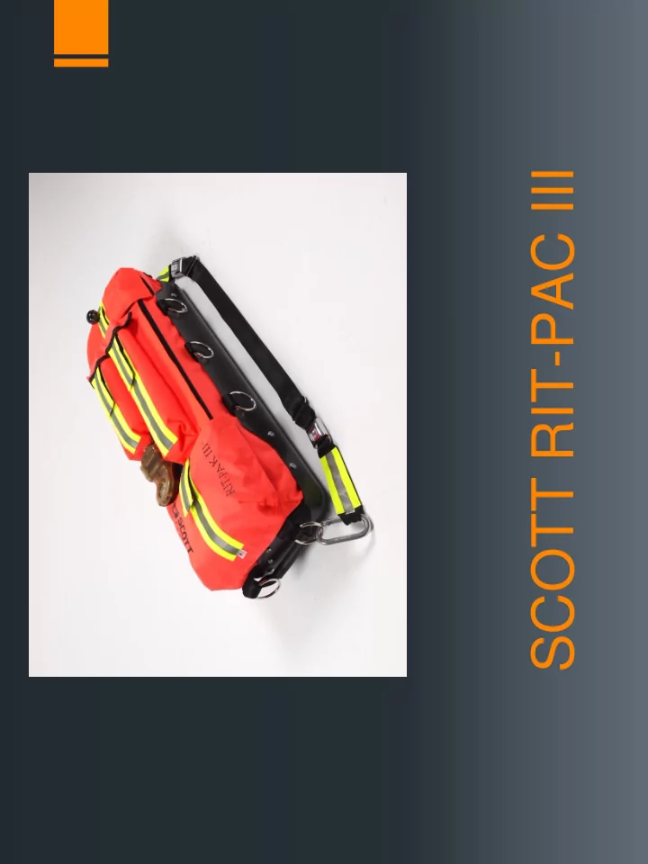
SCOTT RIT-PAC III Objectives Describe the SCOTT RIT-PAC III and its components Daily check and inspection Basic Operation List and describe the options you have with the low pressure side of the pack Describe and


slide-1
SLIDE 1

SCOTT RIT-PAC III

slide-2
SLIDE 2

Objectives

  • Describe the SCOTT RIT-PAC III and it’s components
  • Daily check and inspection
  • Basic Operation
  • List and describe the options you have with the low pressure

side of the pack

  • Describe and go over the procedures of the high pressure

side of the pack

  • The procedure for changing the Remote Pressure Gauge

batteries

slide-3
SLIDE 3

Description

Definition-Portable air supply intended for use by a Rapid Intervention Team as an emergency source of breathing air to supply a single down Firefighter while that person is being extricated from a IDLH atmosphere.

slide-4
SLIDE 4

The Bag

  • T-Handle is on the high pressure side of the bag
  • Ball-Handle is on the low pressure side of the bag
  • Dedicated rigid compartments to store the High and Low

pressure supply hoses

  • The top cover has two additional soft storage compartments
  • The skid plate protects the bottom and sides of the bag
slide-5
SLIDE 5

High/Low Pressure Lines

  • Low Pressure Hose is 6’ Long
  • The low pressure manifold has male and female quick

connect couplings for Scott and Interspiro

  • High Pressure Hose is 5’ long
  • The high pressure hose has a Rapid Intervention Crew

Universal Air Connection (RIC UAC) fitting.

slide-6
SLIDE 6

Air Bottle

  • SCOTT 4.5 Cylinder
  • 4500psi.
  • 60 minute rated air supply
slide-7
SLIDE 7

Remote Gauge Console

  • Analog gauge showing the total available air pressure left in

your air cylinder

  • LED display with lights indicating the remaining air in the

same format as the heads-up display

  • There is a round red low battery light
slide-8
SLIDE 8

Pressure Reducer

  • Reduces bottle pressure to 160psi. And delivers it to the low

pressure side

  • Built in bell which sounds at ¼ bottle pressure or 1000psi.
slide-9
SLIDE 9

Facepiece/Emergency Breathing Regulator

  • The mask is a special configuration of the AV3000 SureSeal

facepiece

  • It has no nose cup or voice mitters
  • There is a special head harness with large rings built in to the

securing straps

  • Emergency Breathing Regulator has no heads-up display or

low air vibralert

slide-10
SLIDE 10

Daily Check/Inspection

  • The RIT pack must be inspected at the start of each shift.
slide-11
SLIDE 11

Bottle Inspection

  • Check for the latest hydrostatic test date and make sure it is

within 5 years

  • Make sure the bottle is within 15 years of the manufacture

date

  • Visually inspect the cylinder for and obvious damage
  • Check the cylinder pressure for fullness or above 4000psi.
slide-12
SLIDE 12

RIT Bag Inspection

  • Any signs of damage or contamination
  • Make sure the shoulder strap seat belt buckles work and the

carabineers open and close freely

  • All rings are attached and in place
  • Check hard plastic bottom for any cracks or holes
slide-13
SLIDE 13

Hoses/Facepiece/Regulator Inspection

  • Fully extend high/low pressure hoses from storage

compartments and check for damage and contamination

  • Check mask for cleanliness and damage
  • Make sure straps on head harness are fully extended
  • Visually inspect the regulator and regulator hose for damage
  • Check the male coupling on the emergency regulator hose

for damage and ware

slide-14
SLIDE 14

Basic Operation

  • Turn the cylinder valve on and listen for leaks
  • Observe the LED display on the remote gauge and make

sure all 5 lights stay lit for 20 seconds. Followed by the light which marks the air level.

  • Check the remote pressure gauge and make sure it is within

10% of the bottle pressure

slide-15
SLIDE 15

Basic Operation Cont.

  • Attach regulator to mask and don the mask
  • Check the air saver/donning switch and purge valve for

proper operation

  • Remove the facepiece and make sure the regulator free

flows by pushing the air saver/donning switch

  • Turn bottle off
slide-16
SLIDE 16

Basic Operation Cont.

  • Bleed the purge valve and observe the pressure indicator

lights to make sure they are all operational

  • Make sure low air bell sounds at ¼ bottle pressure or

1000psi.

slide-17
SLIDE 17

Low Pressure Air Supply

  • Description
  • Options of the Low Pressure System
slide-18
SLIDE 18

Low Pressure Air Supply Description

  • The low pressure hose is 78” long
  • The low pressure air supply is to replace the depleted air

cylinder of the firefighters SCBA or to supply breathing air to the firefighter with a facepiece and regulator

slide-19
SLIDE 19

Low Air Supply Options

  • Connecting to buddy breather hose or EBSS (emergency

breathing support system)

  • Connecting emergency breathing regulator
  • Use of emergency facepiece and emergency regulator
  • Connecting to the Inerspiro buddy breathing ports
slide-20
SLIDE 20

Connecting to Buddy Breather Hose

  • Connect the victims Buddy Breather low pressure hose to

either of your male or female quick connect coupling on the low pressure regulator

  • If victims cylinder valve is open air will continue to be

supplied from their cylinder until the pressure drops below the supply pressure from the low pressure air line assembly

slide-21
SLIDE 21

Connecting To Buddy Breather Hose Cont.

  • If victims cylinder valve is off or his bottle is empty the only

source of air will be from the RIC Pack

  • This is the way to deliver the longest breathing time to the

victim

  • The victim gets the 60min. bottle plus whatever he has left in

his bottle

slide-22
SLIDE 22

Connecting to Buddy Breather Hose Cont.

  • This method is the fastest and easiest
  • If victim is entrapped it gives him the longest time to breathe

for extended extrication

  • The victims facepiece and regulator must be intact and

working

slide-23
SLIDE 23

Indications for Connecting Emergency Breathing Regulator

  • The victims SCBA does not have any quick disconnects

suitable for attachment

  • The regulator is clearly damaged
  • If the fastest way to provide breathing air is to replace the

victims breathing regulator

slide-24
SLIDE 24

Connecting Emergency Breathing Regulator

  • Make sure the regulator is attached to low pressure manifold
  • Attach to victims facepiece with a ¼ turn and make sure the

regulator locks

  • If air saver/donning switch does not open from the victim

breathing, open the purge valve to supply the victim with air

  • Secure low pressure hose to victim
slide-25
SLIDE 25

Indications for Administering the Emergency Facepiece

  • The victims air pack is not compatible with the SCOTT air

packs or RIT Pack III

  • The victims facepiece is damaged
  • The victim is not wearing a facepiece or an SCBA at all
slide-26
SLIDE 26

Administering the Emergency Facepiece

  • Make sure the facepiece is attached to the regulator and the

regulator is attached to the low pressure manifold

  • Loosen existing facepiece harness and hold the facepiece

against the victims face

  • Quickly remove the victims facepiece and replace it with the

emergency facepiece

slide-27
SLIDE 27

Administering the Emergency Facepiece Cont.

  • If the saver/donning switch does not open from the victim

breathing, open the purge valve to supply the victim with air

  • Secure the mask to victim by tightening head harness straps

from bottom to top

  • Secure low pressure hose to victim
slide-28
SLIDE 28

Indications for Buddy breathing with Interspiro connections

  • Victim has an Interspiro SCBA
  • Victim has an intact facepiece and an operational Interspiro

SCBA

slide-29
SLIDE 29

Buddy Breathing with Interspiro Connections

  • Connect the victims low pressure hose to either of your male
  • r female Interspiro quick connect coupling on the low

pressure regulator

  • You can connect to the victims buddy breather port on their

right shoulder. It is male connection only

  • Check connection with a tug
slide-30
SLIDE 30

High Pressure Air Supply

  • Description
  • Indications
  • Procedure
slide-31
SLIDE 31

High Pressure Air Supply Description

  • The high pressure hose is 67” long
  • It is bottle pressure
  • It is a RIC UAC connection which came from NFPA 1981.

You’ll find them on 2002 SCBA models and newer

  • The High pressure air supply is to partially recharge the

depleted air cylinder of a firefighters SCBA

slide-32
SLIDE 32

High Pressure Air Supply Description Cont.

  • The male RIC UAC connection on the SCBA is equipped

with a relief valve which will open when the emergency air supply is greater than the maximum pressure rating of the victims air pack

  • It is for emergency use only
slide-33
SLIDE 33

High Pressure Air Supply Indications

  • A quick fill to aid in a expedient extrication
  • Everything on the victims pack is intact and working
  • Know that you are not supplying the victim with the most air

possible

  • When you can’t be attached to the victim with a buddy

breathing line or regulator

slide-34
SLIDE 34

High Pressure Air Supply Procedure

  • Fully extend the high pressure hose from it’s storage

compartments

  • Remove the dust cover on the female coupling and the dust

cover on the victims air pack

  • Plug the RIC UAC fitting in to the victims pack
  • Observe your RIC packs pressure gauge and the victims

pressure gauge

slide-35
SLIDE 35

High Pressure Air Supply Procedure Cont.

  • Once both bottles have equalized the air will stop flowing
  • Disconnect the high pressure supply hose
  • After charging you may have to repeat this procedure if the

victim gets too low on air again

slide-36
SLIDE 36

Remote Gauge Console Low Battery

  • The low battery light will light for 20sec. And then begin to

flash slowly at once a second.

  • The batteries will have sufficient life to operate the LED

display longer than the longest duration cylinder

slide-37
SLIDE 37

Remote Gauge Console Battery Replacement

  • Remove both battery caps with a Phillips head screwdriver
  • The battery closest to gauge is “-” end out
  • The battery farthest from gauge is “+” end out
  • When covers are back in position the LED display will light

for Approximately 20sec.

  • Tighten both screws hand tight
  • Perform operational inspection to verify proper operation of

LED display

slide-38
SLIDE 38

Battery Installation