Repeaters Ethernet segment is limited to 500 m due to signal - - PowerPoint PPT Presentation

repeaters
SMART_READER_LITE
LIVE PREVIEW

Repeaters Ethernet segment is limited to 500 m due to signal - - PowerPoint PPT Presentation

Repeaters Ethernet segment is limited to 500 m due to signal attenuation Computer Networks A repeater: an analog electronic device continuously monitors electrical signals on each LAN repeats and strengthens/amplifies signal Lecture


slide-1
SLIDE 1

Computer Networks

Lecture 23: LAN Connectivity
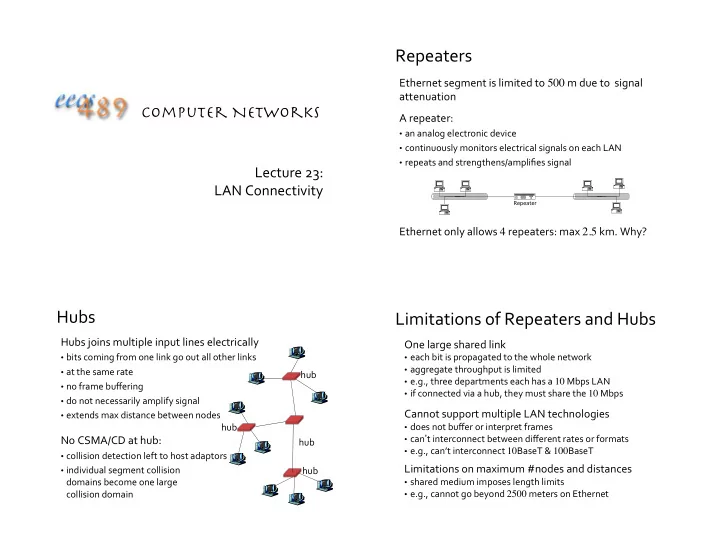
Repeaters

Ethernet segment is limited to 500 m due to signal attenuation A repeater:

  • an analog electronic device
  • continuously monitors electrical signals on each LAN
  • repeats and strengthens/amplifies signal

Ethernet only allows 4 repeaters: max 2.5 km. Why?

Repeater

Hubs

Hubs joins multiple input lines electrically

  • bits coming from one link go out all other links
  • at the same rate
  • no frame buffering
  • do not necessarily amplify signal
  • extends max distance between nodes

No CSMA/CD at hub:

  • collision detection left to host adaptors
  • individual segment collision

domains become one large collision domain hub hub hub hub

Limitations of Repeaters and Hubs

One large shared link

  • each bit is propagated to the whole network
  • aggregate throughput is limited
  • e.g., three departments each has a 10 Mbps LAN
  • if connected via a hub, they must share the 10 Mbps

Cannot support multiple LAN technologies

  • does not buffer or interpret frames
  • can’t interconnect between different rates or formats
  • e.g., can’t interconnect 10BaseT & 100BaseT

Limitations on maximum #nodes and distances

  • shared medium imposes length limits
  • e.g., cannot go beyond 2500 meters on Ethernet
slide-2
SLIDE 2

Switches/Bridges

Link layer router-equivalent:

  • connect LANs at the link layer
  • unlike routers, only know whether

a node is in a segment

  • can connect segments with

different MAC protocols

  • can also connect directly

to host, at full duplex

Store and forward frames between segments

  • extracts destination address from the frame
  • looks up the destination in a table

hub hub hub switch 1 2 3

Bridges/Switches

Support concurrent communication (A C, B D)

  • does not propagate interference and collisions

must buffer

  • when a frame is to be forwarded on a segment,

uses CSMA/CD to access segment

  • increase effective/aggregate bandwidth of a LAN by

taking advantage of spatial locality

host host host host host host host host host host host host

Bridge

A C B D

Transparent Bridges/Switches

Transparent: hosts are unaware of the presence of switches Each switch has a switch table Entry in switch table:

  • <MAC address, interface, timestamp>
  • stale entries in table dropped

(TTL can be 60 mins)

Plug-and-play: self-learning switches do not need to be configured

hub hub hub switch 1 2 3

Backward Learning

How does a switch know at which segment a node is located? Backward learning:

  • when a frame is received, switch “learns” the incoming

interface through which a sender may be reached

  • records sender/interface pair in switch table
slide-3
SLIDE 3

Frame Filtering/Forwarding

When a switch receives a frame: Look for the MAC destination address in switch table if entry found for destination { if destination is on the same segment from which frame arrived {

drop the frame } else { forward the frame on interface indicated }

} else { flood // forward to all interfaces except the incoming interface }

Flooding Example

Suppose C sends a frame to D

Switch receives frame from C records in switch table that C is on interface 1 because D is not in table, switch forwards frame to interfaces 2 and 3 frame received by D

hub hub hub switch A B C D E F G H I address interface A B E G 1 1 2 3

1 2 3

Backward Learning Example

Suppose D now sends a frame to C

Switch receives frame from D records in switch table that D is on interface 2 because C is in table, switch forwards frame

  • nly to interface 1

frame received by C

hub hub hub switch A B C D E F G H I address interface A B E G C D 1 1 2 3 1 2

1 2 3

Switch: Traffic Isolation

Switch breaks subnet into LAN segments Switch filters packets:

  • same-LAN-segment frames are not usually

forwarded onto other LAN segments

  • segments become separate collision domains

hub hub hub switch collision domain collision domain collision domain

slide-4
SLIDE 4

Switches: Dedicated Access

Hosts can have direct connection to switch

  • full duplex: dedicated transmission line

in each direction, still CSMA/CD, but no chance of collision

Switching: A-to-D and B-to-E simultaneously, no collisions Switches can support combinations

  • f shared/dedicated and

10/100/1000 Mbps interfaces

switch A D B E C F

Cut-Through Switching

Buffering delay can be a high fraction of total delay

  • receiving a frame of length L from a link with transmission

rate R takes L/R time units

  • over short distances propagation delay is small
  • and buffering delay can become a large fraction of total

Cut-through switching: streaming transmission

  • inspect the frame header and do the table look-up
  • if outgoing link is idle, immediately start forwarding the

head of the frame to the outgoing link

  • while still receiving the tail via the incoming link

A B

switches

Example Enterprise Network Switch/Hub Installment

hub hub hub switch to external network router IP subnet mail server web server

Cycles and Broadcast Storm

LANs may form cycles

  • either accidentally, or by design, for higher reliability
  • use of flooding can lead to forwarding loops
  • causing “broadcast storm”

To prevent broadcast storm, switches need to avoid some links when flooding, so as not to form a loop How to decide which link to avoid?

slide-5
SLIDE 5

Spanning Tree

What is a spanning tree of a graph?

  • a sub-graph that covers all nodes, but contains no cycle

To avoid loops, links not in the spanning tree do not forward frames Need a distributed algorithm to compute spanning tree

  • switches cooperate to build the spanning tree
  • and adapt automatically when failures occur

[after Rexford]

Constructing a Spanning Tree

Key ingredients of the algorithm

  • switches need to elect a “root”
  • root ::= the switch with the smallest identifier
  • “root messages” of the form (X, R, d) is broadcast
  • X is the ID of the node sending/forwarding the root message
  • R is the current root (smallest ID seen)
  • d is X’s cost/distance to R
  • each switch checks whether its interface is on the

shortest path from the root

  • exclude from the spanning tree interfaces not on the shortest path

from root, break tie by ID

  • each LAN has a designated switch
  • multiple switches elect one with shortest root path, break tie by ID

[after Rexford]

Steps in Spanning Tree Algorithm

Initially, each switch thinks it is the root

  • switch sends a root message out every interface
  • identifying itself as the root with distance 0
  • example: switch X announces (X, X, 0)

Switches update their “root view”

  • upon receiving a root message, check the root id
  • if the new id is smaller, start viewing that switch as root

Switches compute their distance from the root

  • add 1 to the distance received from a neighbor
  • identify interfaces not on a shortest path to the root
  • and exclude them from the spanning tree
  • flood an updated root message

[after Rexford]

Example from Switch 4’s Viewpoint

Switch 4 thinks it is the root

  • sends (4, 4, 0) root message to 2 and 7

Then, switch 4 hears from switch 2

  • receives (2, 2, 0) root message from 2
  • and thinks that switch 2 is the root
  • at distance one hop away

Then, switch 4 hears from switch 7

  • receives (7, 2, 1) from 7
  • realizes that this is a longer path
  • so, prefers its own 1-hop path (on root port)
  • and removes 4-7 link from the tree

1 2 3 4 5 6 7

[after Rexford]

slide-6
SLIDE 6

Switch 2 hears about switch 1

  • switch 2 hears (3, 1, 1) from 3
  • switch 2 starts treating 1 as root
  • and sends (2, 1, 2) to neighbors

Switch 4 hears from switch 2

  • switch 4 starts treating 1 as root
  • and sends (4, 1, 3) to neighbors

Switch 4 hears from switch 7

  • switch 4 receives (7, 1, 3) from 7
  • and realizes that this is a longer path
  • prefers its own 3-hop path (on root port)
  • and removes 4-7 Iink from the tree

Example from Switch 4’s Viewpoint

1 2 3 4 5 6 7

[after Rexford]

Robust Spanning-Tree Algorithm

Algorithm must react to failures

  • failure of the root node
  • need to elect a new root, with the next lowest identifier
  • failure of other switches and links
  • need to re-compute the spanning tree

Root switch continues to send root messages

  • periodically re-announces itself as the root (1, 1, 0)
  • other switches continue to forward root messages

Detect failures through timeout (soft state)

  • a switch waits to hear from others
  • eventually times out and claims to be the root, and

restarts the distributed algorithm all over again

[after Rexford]

Forwarding on Spanning Tree

Summary of distributed spanning tree computation:

  • switch with lowest ID becomes root of tree
  • all switches (except root) determine root port (port to root)
  • the spanning tree consists of

switches and root-port links

  • designated-port links connect

designated switches to LANs

Forwarding on the tree:

  • forward frames only on root-port and

designated-port links

  • tree does not provide shortest path, e.g.,

A to C does not go through B3

Peterson & Davie

Advantages of Switches

  • ver Hubs/Repeaters

Only forwards frames as needed

  • filters frames to avoid unnecessary load on segments
  • sends frames only to segments that need to see them

Extends the geographic span of the network

  • separate segments allow longer distances

Improves privacy by limiting scope of frames

  • hosts can “snoop” only the traffic traversing their segment

Can join segments using different technologies

[after Rexford]

slide-7
SLIDE 7

Disadvantages of Switches

  • ver Hubs/Repeaters

Delay in forwarding frames

  • bridge/switch must receive and parse the frame
  • and perform a look-up to decide where to forward
  • storing and forwarding the packet introduces delay
  • solution: cut-through switching

Need to learn where to forward frames

  • bridge/switch needs to construct a forwarding table
  • ideally, without intervention from network administrators
  • solution: self-learning

Higher cost

  • more complicated devices cost more money

[after Rexford]

Switches vs. Routers

Both store-and-forward devices Given bridges/switches, why do we still need routers?

  • routers are network layer devices (what does this mean?)
  • routers maintain routing tables, implement routing algorithms
  • switches are link layer devices
  • switches maintain switch tables, implement filtering, backward

learning algorithms

Switch

Segment vs. Subnet

A commonly used differentiator:

  • segment: a layer-2 collision domain
  • subnet: a layer-3 broadcast domain

A subnet may contain multiple segments A segment may contain multiple subnets (not recommended) “Segment” is also often used to simply mean “part of a network” not always according to a precise technical definition

Moving From Switches to Routers

Advantages of switches over routers

  • plug-and-play
  • fast filtering and forwarding of frames

Disadvantages of switches over routers

  • topology is restricted to a spanning tree
  • large networks require large ARP tables
  • broadcast storms can cause network collapse

[after Rexford]

slide-8
SLIDE 8

Comparing Hubs, Switches, Routers

Hub/ Repeater Bridge/ Switch Router Traffic isolation ✗ ✔ ✔ Plug and Play ✔ ✔ ✗ Efficient routing ✗ ✗ ✔ Cut through ✔ ✔ ✗

[after Rexford]

Evolution Toward Virtual LANs

When being part of a LAN means tapping into a cable that passes through one’s office

  • people in adjacent offices were put on the same LAN
  • regardless of their functional role

With hubs and switches sitting in central wiring closets, often with multiple LANs (k hubs) connected by switches

  • adjacent offices can be

mapped to different LANs

[after Rexford]

hub hub switch

wiring closet

Why Group by Organizational Structure?

Security

  • Ethernet is a shared media
  • any interface card can be put into “promiscuous” mode
  • and get a copy of all of the traffic (e.g., midterm exam)
  • so, isolating traffic on separate LANs improves security

Load

  • some LAN segments are more heavily used than others
  • e.g., researchers running experiments that get out of hand can

saturate their own segment and not the others

  • plus, there may be natural locality of communication
  • e.g., traffic between people in the same research group

[after Rexford]

LAN Reconfiguration

Organizational changes are frequent

  • administrative office becomes a marketing office
  • technical support personnel becomes an administrative personnel
  • as people change role, their machines move from one LAN to

another

Physical rewiring is a major pain

  • requires unplugging the cable from one port
  • and plugging it into another
  • and hoping the cable is long enough to reach
  • and hoping you don’t make a mistake

Would like to “rewire” the building in software

  • the resulting concept is a Virtual LAN (VLAN)

[after Rexford]

slide-9
SLIDE 9

VLANs Implementations

Add configuration tables at bridges/switches

  • saying which VLANs are accessible via which interfaces

Approaches to VLAN mapping:

  • give each interface a VLAN “color”
  • only works if all hosts on the same segment belong to the same VLAN
  • give each MAC address a VLAN “color”
  • useful when hosts on the same segment belong to different VLANs
  • useful when hosts move from one physical location to another

Change Ethernet header

  • add a field for VLAN tag
  • recognized by bridges/switches only
  • ignored by old Ethernet cards

[after Rexford]

Example: Two Virtual LANs

Red VLAN and Orange VLAN Switches forward traffic as needed

R O RO R R R O O O R O R R R O O O

[Rexford]

Red VLAN and Orange VLAN Bridges forward traffic as needed

R RO RO O RO

Example: Two Virtual LANs

[Rexford]

Ethernet Switches

Independent

  • follow their own rules
  • determine their own forwarding path
  • responsible for VLAN and other services
  • communicate topology information with their peers

Once a person/host gets on an Ethernet network, it can do anything What if we want to have finer control of what a host/person can do on a LAN?

slide-10
SLIDE 10

Ethane: a Prototype Software-Defined Network (SDN)

Centralized Network Control

  • network rules enforced by network controller
  • controller monitors and approves all traffic
  • allows for complete policy-based control of the network
  • access controls built in
  • network understands users,

hardware, topology, and policies

  • controller responsible for

damage-routing

[C+5]

Flow Setup Process

  • 1. UserA tries to connect to UserB
  • 2. UserA to UserB flow isn’t in Switch 1’s flow table,

so the packet is forwarded to the Controller

  • 3. Controller either approves or denies route
  • 4. If approved, Switch 1 and

Switch 2 establish a flow from UserA to UserB

[C+5]

Ethane’s Assumptions

Policy determines packet flow Network should maintain a strong connection between users and traffic Bake security into network policy Policy should be simple to implement Incremental deployability

  • should work with Ethernet

Ethane Policy Configuration

The configuration language for Ethane:

  • compiled into controller
  • individual rules are ANDed
  • f simple statements
  • allows for user-based rules
  • rules priority determined

by order in file

  • very human-readable

[C+5]

slide-11
SLIDE 11

Dependent on controller

  • requires connection to controller to route new traffic
  • communicates with controller over a secure channel

Simple

  • minimal on-board logic
  • “flow” table lookup only
  • only stores active flows
  • no understanding of network topology
  • no NAT knowledge
  • no VLAN support

SDN Switches Flow Table Entry

Type 0 OpenFlow Switch

Switch port MAC src MAC dst Eth type VLAN ID IP src IP dst IP prot TCP sport TCP dport

Rule Action Stats

  • 1. Forward packet to port(s)
  • 2. Encapsulate and forward to controller
  • 3. Drop packet
  • 4. Send to normal processing pipeline

+ mask

Packet + byte counters

The Network Controller

Switches report network topology to Network Controller (NC)

  • NC uses this to create flow rules

Controls all routes between hosts

  • allows for prioritization
  • NC handles congestion
  • can restrict client movement

Handles Authentication

  • users, devices, switches
  • understands where a user is

physically connected to the network

The Network Controller

Informed of link failures and updates flow rules Can cut off misbehaving hosts at the switch, completely denying network access Supports resource limits on clients Handles broadcast requests Allows for very detailed network usage logs

  • useful for failure post-mortems
  • presents something of a privacy risk

[C+5]

slide-12
SLIDE 12

SDN not Limited to LAN

B4: Google’s WAN

  • connects a few dozen WAN data centers
  • has been in deployment since July 2010
  • most traffic carried: synchronizing large data sets
  • uses SDN and OpenFlow to implement Traffic Engineering
  • control of edge sites and applications:
  • re-route traffic to less congested path
  • schedule backup traffic to quiet time