
SLIDE 1
Production Target at J-PARC Hadron Experimental Facility
Hitoshi Takahashi KEK / J-PARC Center
Production Target at J-PARC Hadron Experimental Facility Hitoshi - - PowerPoint PPT Presentation
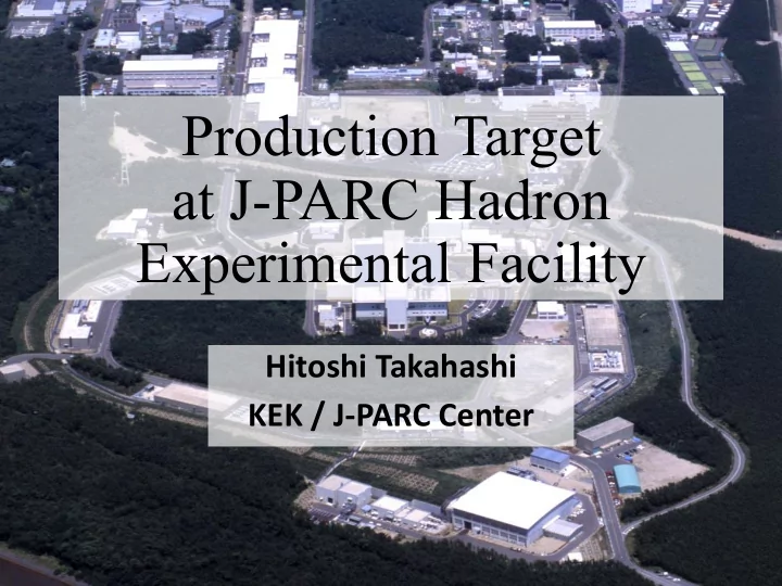
Production Target at J-PARC Hadron Experimental Facility Hitoshi Takahashi KEK / J-PARC Center RCS n Hadron Birds eye photo in July, 2009 Hadron Experimental Facility (HD-hall) T1 target beam dump (50% loss) Extraction
Hitoshi Takahashi KEK / J-PARC Center
RCS
Bird’s eye photo in July, 2009
Hadron Experimental Facility (HD-hall)
T1 target (50% loss) beam dump
K1.8 (K1.1) KL K1.8BR
Extraction from 50GeV MR
Switch Yard: 200m
(High-p)
HD-hall: 56m ü Various secondary beams: p, K, p-bar, …. ü Currently only one production target: T1 ü KL: kaon rare decay ü K1.8, K1.8BR, (K1.1): strangeness nuclear physics, etc. ü New primary beam lines are now under construction (high-p, COMET)
(COMET)
antiprotons, ...) for particle and nuclear physics experiments
→ Point source is desirable in order to separate secondary particles.
→ Point source is desirable in order to reduce experimental background.
① Large mass number and high density for intensity and quality of secondary beams ② Radiation hardness and chemical stability for stable operation ③ Sufficient cooling efficiency for high-intensity beam
K1.8BR K1.8 K1.1 (under construction) KL
T1 target
Proton beam
2s 5.52s Beam intensity time slow extraction beam
Beam conditions
repetition
Gold (6-divided)
Ø Up to 50 kW beam Ø Indirectly water-cooled Ø Gold was chosen due to the good thermal conductivity and thermal expansion coefficient close to that of copper Ø Involved in airtight chamber and He gas is circulated to monitor the target soundness Proton beam Cooling water Target replacement using target driver Copper Stainless-steel *Gold, copper, and stainless-steel are bonded by HIP (Hot Isostatic Pressing) 66mm Cross-sectional view
target chamber
He He
Since the beam windows are always exposed to a primary beam directly, we designed the windows to keep their soundness even in the case of 5-µs pulse beams. * 5-µs = revolution of Main Ring
Fittings for remote lifting
Front view
Water (bored-through connectors) Thermocouple (hermetic connector) Target Driver
Gold target
Beam Airtight chamber Beam windows
Circulating pump (5m3/h), Filter, Monitors
Target chamber (0.23m3) Gas piping (total 180m) Gas storage tank (1.7m3) Gas storage tank (1.7m3) 2nd machine bldg. Hadron experimental hall Proton beam
tank within 30 min.
Ø Installation: Sep. 2014 Ø Beam ope.: Apr. 2015 - Measured temperature was in good agreement with calculation Temperature of each gold piece is measured with thermocouples every 100ms
6 1.5 f0.5mm sheath thermocouples
Copper
Beam
1 2 3 4 5 6
50 100 150 200 250 300 350 10 20 30 40 50
Beam power (kW) data calc
Temperature @41.6kW
max 297℃(ΔT=267K)
beam-power dependence
structure
6
Ready to manufacture
1 MN MX X Y Z t161128(Au ƒÐ2.5,1.0) @ 30GeV-9.19e13ppp @5.52s-cycle c1 1 MN MX X Y Z sold-target161128(Au0-6,ƒÐ2.5,1.0) @ 30GeV-9.19e13ppp @ 5.52s, c1beam
max 333°C vertical expansion: max 0.10mm bonded interface 46MPa bonded interface 237°C
temperature beam
(Only the lower block is shown)
Results of thermal analysis (80kW, 5.52s cycle)
Design margin: 2.7 von Mises stress
View from upstream
beam max 72°C (DT=42K) beam bonded interface 6.3MPa von Mises stress temperature water cooled
1 MN MX X Y Z kaiten120-346-1P-He (Au-Ni,ƒÐ2.5,1.0) @ 30GeV-187.2e13ppp @ 100w/m2/k 1 MN MX X Y Z sold-kaiten120-346-1P-He (Au-Ni,ƒÐ2.5,1.0) @ 30GeV-18.72e13ppp @beam max 200°C (DT=170K) beam bonded interface 15MPa He gas cooled
Results of thermal analysis (Au, 150kW, 5.52s cycle)
thermal stress is considerably smaller than that of indirectly cooled target
Au or Pt Ni
issues:
No need for motor and long shaft
can be achieved easily
components in high- radiation area
Previous design
motor shield blocks rotating disk target
New idea water turbine He gas turbine
generation
circulation system
system
He gas
H gas, and tritium generation)
system
circulation system
Electron Beam Welding
Hot Isostatic Pressing
between Au(Pt) and Ni
Au or Pt Ni
Au Ni Alloy Pt Ni Alloy
Au + Ni Pt + Ni 10mm Au + Ni
pump
disassembling and modifying a commercial blast fan
(f8mm) gas turbine mockup for target disks (iron) gas blow bearing
Next step
50 100 150 200 250 300 350 400 450 500 20 40 60 80 100
Rotation speed (rpm) Time (min.)
120rpm
Target disks can be driven even with flow rate
assumption in thermal analysis
rotating disk gas blow
Single disk 3 disks Single disk
Simple flat disk(s) Spoke-type disk(s)
3 disks
Cooling efficiency for the inner disk compared with the outer disks
Current: Titanium alloy (Ti-6Al-4V)
OK up to 107 cycles (~ 15k hours)
deformation: will reach the endurance limit (1 %) in ~50 kW x 7.5k hours => This limited the life of current target
Next: Beryllium or Titanium alloy
(with improved cooling)
Nickel flange (brazed to Be)
Beryllium (f460-t8mm) Titanium alloy (f300-t4mm)
Soundness of Be windows (80kW)
Material Case Estimated Stress Allowable Stress
Upstream Beryllium 3 mmt
Maximum static stress by atmospheric pressure
48 MPa (edge) 31 MPa (center) 133 MPa
(1.5xSM @100°C)
Equivalent stress amplitude in normal
Shot by shot
3.7 MPa (DT=3.6K) 126 MPa
(107 fatigue str. @100°C x1/2)
Average temp.
3.8 MPa (DT=3.9K) 126 MPa
(104 fatigue str. @100°C x1/2)
Thermal stress range by 5-µs beam
166 MPa (DT=93K) 256 MPa
(3xSM @150°C)
Downstream Beryllium 6 mmt
Maximum static stress by atmospheric pressure
42 MPa (edge) 27 MPa (center) 133 MPa
(1.5xSM @100°C)
Equivalent stress amplitude in normal
Shot by shot
2.8 MPa (DT=3.2K) 126 MPa
(107 fatigue str. @100°C x1/2)
Average temp.
17.2 MPa (DT=18K) 126 MPa
(104 fatigue str. @100°C x1/2)
Thermal stress range by 5-µs beam
151 MPa (DT=93K) 256 MPa
(3xSM @150°C)
*allowable stresses are according to JIS-B8266.(construction for pressure vessels)
SM: design stress intensity (=UTS/3.5)
In all cases, estimated stress are lower than allowable stress.
Soundness of Ti-alloy windows (80kW)
Material Case Estimated Stress Allowable Stress
Upstream Ti-alloy (6Al,4V) 2 mmt
Maximum static stress by atmospheric pressure
145 MPa (edge) 176 MPa (center) 430 MPa
(1.5xSM @450°C)
Equivalent stress amplitude in normal
Shot by shot
53 MPa (DT=138K) 206 MPa
(107 fatigue str. @450°C x1/2)
Average temp.
80 MPa (DT=153K) 306 MPa
(104 fatigue str. @400°C x1/2)
Thermal stress range by 5-µs beam
242 MPa (DT=480K) 502 MPa
(3xSM @600°C)
Downstream Ti-alloy (6Al,4V) 4 mmt
Maximum static stress by atmospheric pressure
119 MPa (edge) 162 MPa (center) 430 MPa
(1.5xSM @450°C)
Equivalent stress amplitude in normal
Shot by shot
21 MPa (DT=82K) 206 MPa
(107 fatigue str. @450°C x1/2)
Average temp.
148 MPa (DT=351K) 306 MPa
(104 fatigue str. @400°C x1/2)
Thermal stress range by 5-µs beam
234 MPa (DT=350K) 310 MPa
(3xSM @800°C)
*allowable stresses are according to JIS-B8266.(construction for pressure vessels)
SM: design stress intensity (=UTS/3.5)
In all cases, estimated stress are lower than allowable stress.
Peak radiation damage (R=0mm) Residual dose at contact after 3 months cooling Radioactivity after 10 min. cooling
Ti-alloy (6Al,4V) 1.2 DPA 980 mSv/h 46 GBq (57 nuclides) Beryllium 0.014 DPA 6.3 mSv/h 2.7 GBq (2 nuclides)
Both damage rate and radioactivity for Be are much lower than those for Ti alloy. After 80kW x 2500 hours (= 1.5 x 10²⁰ protons) irradiation Estimated by PHITS(damage, radioactivity) and MARS(residual dose)
Other beam windows we use:
Thin Aluminum-alloy (Al-4.5Mg-0.7Mn, or Al-4.5Zn-2Mg) for vacuum separation between high- and low-vacuum sections
We are very interested in the radiation- damage effects for these materials.
Around 7 DPA
75-125℃ D.S.Gelles et al,
Strength of Be after irradiation Aluminum-alloy (f200-t0.1mm)
detail analysis is in progress.
Stress estimation for 270kW beam.
(heat capacity) of the gold target exposed to the beam.
The temperature rise of the new target with the 100kW beam in 1 spill is higher than the 50kW case of the current target
6
cooling (adiabatic)
cooling
Cooling effect (twice as large as before) Depends on specific heat (same as before)
Temperature Time
26
6mm 12mm 6mm 15mm 5mm 2mm 2mm Current 50kW target Next 80kW target
Size of gold is optimized for secondary-beam yield and cooling efficiency.
flat top 2.92s ramping up/down 2.6s beam
max 308°C
These are simple estimations by assuming allowed temperature rise is same as that for 5.52s cycle and 80kW. Detailed consideration is needed to determine the maximum power for
current spill structure
87kW?
flat top: 2.92s => 2.4s (5s cycle, 80kW) beam
max 248°C
111kW?
moreover, ramping up/down: 2.6s => 1.3s (3.7s cycle, 80kW)
Time projection of vertical beam position measured with the profile monitor just upstream of the target in previous run very stable in rage of +/- 0.5mm
28
ANSYS 15.0 DEC 6 2016 NODAL SOLUTION STEP=58 SUB =8 TIME=106.88 TEMP (AVG) RSYS=0 PowerGraphics EFACET=1 AVRES=Mat SMN =33.0152 SMX =374.765 1
MN MXX Y Z 33.0152 54.3746 75.7339 97.0932 118.453 139.812 161.171 182.531 203.89 225.249 246.609 267.968 289.327 310.687 332.046 353.405 374.765 t161128(Au ƒÐ2.5,1.0) @ 30GeV-9.19e13ppp @5.52s-cycle c1 y-0.0005 ANSYS 15.0 DEC 6 2016 NODAL SOLUTION STEP=4 SUB =10 TIME=2 SEQV (AVG) RSYS=0 DMX =.104E-03 SMN =168385 SMX =.797E+08 1
MN MXX Y Z 168385 .514E+07 .101E+08 .151E+08 .200E+08 .250E+08 .300E+08 .350E+08 .399E+08 .449E+08 .499E+08 .548E+08 .598E+08 .648E+08 .697E+08 .747E+08 .797E+08 sold-target161128(Au0-6,ƒÐ2.5,1.0) @ 30GeV-9.19e13ppp @ 5.52s, y-0.0005 c1
beam Design margin: 2.3
bonded interface 52MPa
von Mises stress temperature beam
In case beam shifts 0.5mm lower continuously
upper gold max 280°C lower gold max 375°C upper bonded interface 200°C lower bonded interface 266°C
vertical expansion: upper gold: max 0.08mm lower gold: max 0.10mm
Bonding strength: 171MPa(@25°C) 137MPa(@200°C) 76MPa(@400°C) linear interpolation: 117MPa(@266°C)
DEC 6 2016 NODAL SOLUTION STEP=61 SUB =8 TIME=112.4 TEMP (AVG) RSYS=0 PowerGraphics EFACET=1 AVRES=Mat SMN =32.675 SMX =411.991 1
MN MXX Y Z 32.675 56.3823 80.0895 103.797 127.504 151.211 174.919 198.626 222.333 246.04 269.748 293.455 317.162 340.869 364.577 388.284 411.991 t161128(Au ƒÐ2.5,1.0) @ 30GeV-9.19e13ppp @5.52s-cycle c1 y-0.001(21st) ANSYS 15.0 DEC 6 2016 NODAL SOLUTION STEP=4 SUB =10 TIME=2 SEQV (AVG) RSYS=0 DMX =.113E-03 SMN =142717 SMX =.926E+08 1
MN MXX Y Z 142717 .592E+07 .117E+08 .175E+08 .233E+08 .290E+08 .348E+08 .406E+08 .464E+08 .521E+08 .579E+08 .637E+08 .695E+08 .752E+08 .810E+08 .868E+08 .926E+08 sold-target161128(Au0-6,ƒÐ2.5,1.0) @ 30GeV-9.19e13ppp @ 5.52s,c1,y-0.001(21st)
beam Design margin: 2.0
bonded interface 54MPa
von Mises stress temperature beam
In case beam shifts 1mm lower in 1 spill
upper gold max 236°C lower gold max 412°C upper bonded interface 174°C lower bonded interface 295°C
vertical expansion: upper gold: max 0.07mm lower gold: max 0.11mm
Bonding strength: 171MPa(@25°C) 137MPa(@200°C) 76MPa(@400°C) linear interpolation: 108MPa(@295°C)
Such an unusual beam can be detected by plural monitors (target temperature, profile monitor, magnet current) and be aborted during spill “SX Abort”
HD Beam Loss Target Temperature Instantaneous Rate of the primary beam Instantaneous Rate of the 2ndry particle MR Beam Loss in SX region EQ Current Deviation SX-Abort Resonance Sextupole Off EQ Off SX Bump Magnets off (keeping orbit closed)
Monitors for Abnormal Extraction Detection
Extraction stops even after the extraction started, and the beam continues to circulate in the MR, and is kicked to the aborting dump at the end of the spill.
abnormal hit of the primary beam.
Ripples, etc. Malfunction etc. 31
HD 2ndry particle rate monitor
④ over the threshold à SX-Abort
② Acceleration ③ SX ⑤ SX was stopped ⑥ Aborted
Particle number in MR
2015-12-17 03:23 RUN65 shot 397185
Unusual beam
Normal operation
Particle number in MR
2ndry particle counts (/1ms) 2ndry particle counts (/1ms) 200 100
proton number in MR (x10^13)
HD 2ndry particle rate monitor
The system worked properly, and protected hadron equipment several times during the fall beam time.
32
Basic R&D for cooling efficiency by gas
Thermography shows the heat distribution is uniform Rotation unit with a disk, in which a heater cable is embed.
calibration)
ファイバーで赤外線を伝達するタイプの放射温度計が昨年度に発売された from ジャパンセンサー(おもに高温測定用)
ファイバー (石英単芯) レンズ(CaF2、 LaSF光学ガラス) 温度変換機 (InGaAs素子)
100℃から1500℃ (ファイバーを10mにすると測定下限150℃)
Gold coat (foundation: Ni, body: Cu)
quarts fiber lens soldering iron quarts plate focus position can be seen by LED
0 rpm, w/o blower, radiation factor = 0.076
commercial radiometer ΔT 50K -> 0.15mV output 0.003 mV/K/9cm2
y = 0.417x - 0.0031 R² = 0.98772 y = 0.3627x + 0.0294 R² = 0.98209
0.05 0.1 0.15 0.2 0.25 0.0 0.1 0.2 0.3 0.4 0.5 0.6
輻射計出力電圧(mV)
(T円板4-T輻射計4)・σ・A
冷却側 昇温側
ØRange: 40 - 200 rpm ØAccuracy: within +/- 5% (@120rpm) ØRadiation hardness: > 1000 MGy
Coils are made of ceramic-insulated cables
Magnetic field analysis
P
He gas sprayed to a small hole on the shaft The change of the conductance are measured with a pressure gauge
He
at A
(B) frequently used in BWR motive fluid
Forming test of thick curved platinum plate
Press forming Annealing Production of thick and Long platinum bar. After fine adjustment(forging) Forming of a test peace has been successfully done with good accuracy (radius accuracy of 0.1mm level).
Welding
After fine machining. Materials(pure platinum)
Forming test.
Basic R&D for cooling efficiency by gas
10 20 30 40 50 60 70 80
10000 20000 30000
Temperature rise(K) Time (sec.)
0 rpm without blower 120 rpm without blower 120 rpm with blower
5 10 15 20 25 50 100 150 200 250 Heat-transfer coefficient (W/m2/K) Rotation speed (rpm) With blower Without blower
gas blow (5.8m/s, f90mm) Cooling efficiency for single disk (Preliminary result) rotating disk
force blowing to gap between disks
2mm gap
11 8 7 6 5 4 3 2 1 10 9 12
motor
346mm 2mm 2mm 10mm 50mm 100mm
thermocouples location
Measured efficiency was lower than that of single-disk case Cooling efficiency of 2nd (inner) disk gap dependence improve blowing method groove at surface? spoke structure?
2 4 6 8 10 12 50 100 150 200 250 Heat transfer coefficient (W/m2/K) Rotation speed (rpm)
gap=2mm, with blower (~5.8m/s)
20 40 60 80 20 70 120 170 220
temperature rise [K] beam power [kW]
Au-Ni (φ346mm, 120rpm)
Au Pt
20 40 60 100 200 300
temperature rise [K] rotation speed [rpm]
Au-Ni (φ346mm, 75kW)
Au Pt
10 20 30 200 300 400 500 600
temperature rise [K] disk diameter [mm]
Au-Ni (120rpm, 75kW)
Au temperature rise is
diameter
changed so much over 120 rpm
Water cooled
Beam (σ=2.5x1mm) 5000 W/m2/K 10 W/m2/K f346mm Au or Pt Ni 80mm Temperature of water and He gas were fixed to 30°C beam position is at the top
horizontally wide beam
t11 t11 t11 t21 3
beam He-gas cooled
100 W/m2/K 6mm
side view
beam max 78℃ (DT=48K) beam bonded interface 5.8MPa
ANSYS 14.5 FEB 18 2015 11:01:15 NODAL SOLUTION STEP=58 SUB =4 TIME=116 TEMP (AVG) RSYS=0 PowerGraphics EFACET=1 AVRES=Mat SMN =32.061 SMX =72.3007 1 MN MX X Y Z 32.061 34.576 37.091 39.606 42.1209 44.6359 47.1509 49.6659 52.1808 54.6958 57.2108 59.7258 62.2407 64.7557 67.2707 69.7857 72.3007 kaiten120-346-1 (Au-Ni,ƒÐ2.5,1.0) @ 30GeV-18.72e13ppp @ ANSYS 15.0 FEB 20 2015 10:10:32 NODAL SOLUTION STEP=4 SUB =1 TIME=116 SEQV (AVG) PowerGraphics EFACET=1 AVRES=Mat DMX =.243E-04 SMN =177808 SMX =.631E+07 1 MN MX X Y Z 177808 561336 944865 .133E+07 .171E+07 .210E+07 .248E+07 .286E+07 .325E+07 .363E+07 .401E+07 .440E+07 .478E+07 .516E+07 .555E+07 .593E+07 .631E+07 sold-kaiten120-346-1 (Au-Ni,ƒÐ2.5,1.0) @ 30GeV-18.72e13ppp @beam
150kW, φ346mm, 120rpm
max 72℃ (DT=42K) beam bonded interface 6.3MPa below boiling point of water thermal stress is considerably smaller than that of indirectly cooled target von Mises stress temperature Au Pt
beam max 217℃ (DT=187K) beam bonded interface 18MPa
ANSYS 15.0 MAR 17 2015 10:24:15 NODAL SOLUTION STEP=61 SUB =4 TIME=122 TEMP (AVG) RSYS=0 PowerGraphics EFACET=1 AVRES=Mat SMN =82.6554 SMX =199.814 1 MN MX X Y Z 82.6554 89.9778 97.3002 104.623 111.945 119.267 126.59 133.912 141.235 148.557 155.879 163.202 170.524 177.847 185.169 192.491 199.814 kaiten120-346-1P-He (Au-Ni,ƒÐ2.5,1.0) @ 30GeV-187.2e13ppp @ 100w/m2/k ANSYS 15.0 MAR 17 2015 10:42:51 NODAL SOLUTION STEP=4 SUB =1 TIME=122 SEQV (AVG) PowerGraphics EFACET=1 AVRES=Mat DMX =.268E-03 SMN =.115E+07 SMX =.150E+08 1 MN MX X Y Z .115E+07 .202E+07 .289E+07 .375E+07 .462E+07 .549E+07 .635E+07 .722E+07 .809E+07 .896E+07 .982E+07 .107E+08 .116E+08 .124E+08 .133E+08 .142E+08 .150E+08 sold-kaiten120-346-1P-He (Au-Ni,ƒÐ2.5,1.0) @ 30GeV-18.72e13ppp @beam max 200℃ (DT=170K)
150kW, φ346mm, 120rpm
beam bonded interface 15MPa also thermal stress is smaller than that
von Mises stress temperature Au Pt
beam max 51℃
W, φ346mm, 120rpm, 75kW
beam max 2.9MPa von Mises stress temperature
beam max 196℃
W, φ346mm, 120rpm, 75kW
beam max 9.4MPa von Mises stress temperature
44% loss
the Hadron primary beamline,
(boundary between air pressure):
high and low vacuum:
0.7Mn, or Al-4.5Zn-2Mg)
50kW, (sx2.5mm,sy1mm) :
( estimated by PHITS)
radiation-damage effects for these materials.
Nickel flange (brazed to Be)
Beryllium (φ460-t8mm) Aluminum-alloy (φ200-t0.1mm) Titanium-alloy (φ300-t4mm)