
Brochure No: 9992.0040
PRESENTATION AND SUMMARY OF GEONICA PRODUCTS
GEONICA S.A .A. . Spanish Company founded in 1974, designs, manufactures, installs and maintains Aut utomatic Stations, Systems and Measur uring Networks with Data Transmission, Images and Alarms in Real or Delayed time, for Meteo- rology, Hydrology and Oceanography, as well as for Environmental Monitoring in general. Based on our own line of Automatic Data Acquisition and Transmission Stations, METEODATA/HYD YDRODATA Series, and an advanced and flexible management software, we have integrated all types of sensors to provide complete solutions, systems and measuring networks, intended for different applications on several sectors such as: Mete-
- rology, Hydrology, Water Management and Water Quality, Agriculture, Renewable Energy (Solar and Wind), Coastal
Oceanography, Tides and Waves, Road Safety, Airports and Heliports, Civil Protection, Industry and Mining, environ- mental Noise, Military applications, etc. During our nearly 40 years of business, we have executed hundreds of projects around the World, always in the professional, scientific, industrial and military fields where the highest quality and the strictest technical specifica- tions are required. Below you will find a presentation of our line of products, clasified by sectors, underlining the most important aspects of each of our SYS YSTEMS.
RENEWABLE ENERGY
GEONICA, S.A. - Alejand ndro Rodríguez, nº nº 22 - 28039 Madrid - Spain n Tel. +34 91 450 51 18 Fax +34 91 459 46 14 e-mail: info@geoni nica.com www.geoni nica.com
- 1-
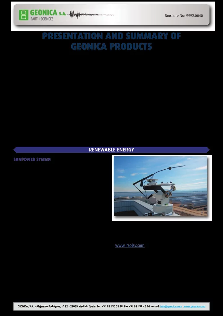
SUNPOWER SYSTEM
Designed for evaluating the location of major thermal and photovoltaic solar plants that, due to the inves- tments worth millions they require, need high quality professional measurement equipment providing reliable
- data. These are essential requirements for the promo-
ters/investors that need to guarantee the return on in- vestments. Likewise, mid- to small-sized solar plants require infor- mation on solar radiation and other weather parameters such as wind, pluviometry, atmospheric pressure, humi- dity and ambient temperature, or even the surface tem- perature of the solar panels themselves, since their performance is affected by all weather conditions. This is one of the flagship lines of our company, with a solidly consolidated position in the national and interna- tional markets offering comprehensive systems for as- sessing the energy resources of the sun, as well as for monitoring photovoltaic (PV) solar Energy, Concentrating Solar Power (CSP), and Concentrated photovoltaics (CPV) plants, since during the operation of a Solar Plant, it is essential to be aware at all times of its performance based on the available energy source ; in this case, global, direct and diffuse solar radiation, depending on the type of technology used. The measurement of the terrestrial irradiance with our equipment installed at the field can be complemented by the analysis of the satellite image in the visible spec- trum performed by our partner company IRSOLAV (www.irsolav.com). The following preliminary documentation is attached with information regarding our SunPower System:
- Brochure No. 9722.0081 Remote Station Model
METEODATA-3000
- Brochure No. 9742.0007 SunPower System Description
- Diagram No. 9785.0057 SunPower System Diagram
- Reference list No. 9993.0015 SunPower System
- Diagram No. 9785.0072 illustrating the Indian Solar
Network, Phase II