possible modes of operation of cms qie
play

Possible modes of operation of CMSQIE (1) Use noninverting mode of - PowerPoint PPT Presentation

Possible modes of operation of CMSQIE (1) Use noninverting mode of QIE: 2.6 fC/count. No practical limit on maximum charge/channel (2) Use calibration mode of QIE: ~1 fC/count. Maximum charge/channel of ~30 fC. (3) Place


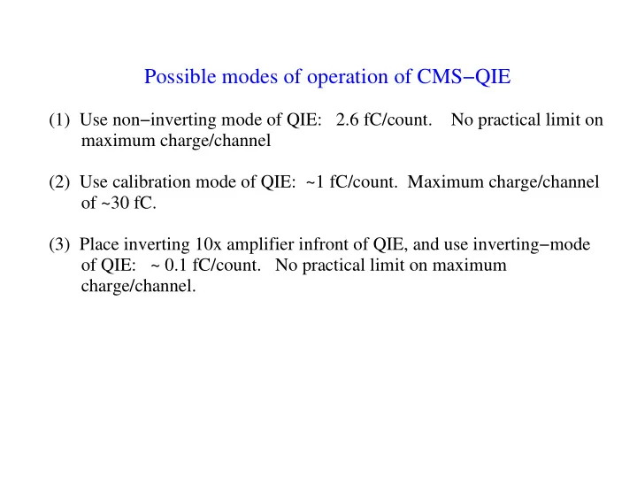
  1. Possible modes of operation of CMS−QIE (1) Use non−inverting mode of QIE: 2.6 fC/count. No practical limit on maximum charge/channel (2) Use calibration mode of QIE: ~1 fC/count. Maximum charge/channel of ~30 fC. (3) Place inverting 10x amplifier infront of QIE, and use inverting−mode of QIE: ~ 0.1 fC/count. No practical limit on maximum charge/channel.

  2. We simulate how well we can reconstruct the beam shape under the following constraints: (1) It is hard to predict the noise level. So we simulate over a wide variety of noise levels (2) The beam width varies from 1.7 mm (at TeV injection) to 0.5 mm (at flattop) (3) The pbar beam amplitude is smaller than protons by ~10x. So we will have to perform a digital sum of many pbar bunches to get adequate resolution. (4) Typical parameters: Number of primary ionizations/bunch: 1000 (p), 100 (pbars) Microchannel plate gain = 1000 (Assume no gain fluctuations and 100% efficiency) Anode strip width = 0.25 mm

  3. Example: protons at injection (1.7 mm bw), Noise=6500e, 1 Sample 4.5 97.92 / 93 131.1 / 93 383.1 / 93 P1 99.10 4.213 P1 9.593 0.3192 P1 3.442 0.5159E-01 12 P2 -0.7483E-01 0.7992E-01 P2 -0.1093 0.5843E-01 P2 -0.3392E-01 0.2443E-01 120 P3 1.697 0.8794E-01 P3 1.584 0.6427E-01 P3 1.420 0.2466E-01 4 10 100 3.5 8 3 80 2.5 6 60 2 4 40 1.5 20 2 1 0 0 0.5 -20 -2 0 -10 0 10 -10 0 10 -10 0 10 Counts (.1 fC/cnt) vs Strip Number Counts (1.0 fC/cnt) vs Strip Number Counts (2.6 fC/cnt) vs Strip Number Note: Errors on the gaussian peaks not quite correct.

  4. Example: protons at flattop (0.5 mm bw), Noise=6500e, 1 Sample 98.88 / 93 116.4 / 93 288.9 / 93 14 P1 336.1 6.844 P1 33.36 0.4503 P1 12.91 0.9047E-01 35 P2 -0.8471E-02 0.1138E-01 P2 -0.1351E-01 0.7475E-02 P2 -0.1333E-01 0.3679E-02 350 P3 0.4879 0.1153E-01 P3 0.4798 0.7429E-02 P3 0.4539 0.3656E-02 12 30 300 10 25 250 8 20 200 6 150 15 4 100 10 2 50 5 0 0 0 -10 0 10 -10 0 10 -10 0 10 Counts (.1 fC/cnt) vs Strip Number Counts (1.0 fC/cnt) vs Strip Number Counts (2.6 fC/cnt) vs Strip Number This operation nearly saturates QIE calibration mode

  5. Example: pbars at injection (1.7 mm bw), Noise=6500e, 36 Samples 5 35 97.68 / 93 107.8 / 93 186.8 / 93 P1 327.4 22.06 P1 22.27 1.539 P1 2.798 0.2178 P2 -0.1261 0.1329 P2 -0.2108 0.1362 P2 0.1018 0.1145 30 P3 1.755 0.1388 P3 1.731 0.1365 P3 1.277 0.1092 400 4 25 300 20 3 200 15 2 10 100 5 1 0 0 0 -5 -100 -10 -1 -200 -10 0 10 -10 0 10 -10 0 10 Counts (.1 fC/cnt) vs Strip Number Counts (1.0 fC/cnt) vs Strip Number Counts (2.6 fC/cnt) vs Strip Number

  6. Example: pbars at flattop (0.5 mm bw), Noise=6500e, 36 Samples 112.0 / 93 122.9 / 93 179.3 / 93 30 P1 1138. 34.57 P1 95.05 2.736 P1 28.73 0.4871 P2 0.4514E-01 0.1737E-01 P2 0.4665E-01 0.1582E-01 P2 0.5150E-01 0.6136E-02 1200 P3 0.4999 0.1759E-01 P3 0.4814 0.1607E-01 P3 0.3195 0.6543E-02 100 25 1000 80 20 800 60 15 600 40 10 400 20 200 5 0 0 0 -10 0 10 -10 0 10 -10 0 10 Counts (.1 fC/cnt) vs Strip Number Counts (1.0 fC/cnt) vs Strip Number Counts (2.6 fC/cnt) vs Strip Number

  7. Example: pbars at flattop (0.5 mm bw), Noise=6500e, 4 Samples 14 3.5 78.85 / 93 76.65 / 93 193.2 / 93 150 P1 121.2 14.57 P1 10.13 1.166 P1 2.540 0.1326 P2 0.1296E-01 0.6767E-01 P2 0.7138E-02 0.5940E-01 P2 -0.9112E-01 0.2458E-01 12 3 P3 0.5001 0.6911E-01 P3 0.4509 0.6144E-01 P3 0.4011 0.2241E-01 125 10 2.5 100 8 2 75 6 1.5 50 4 1 25 2 0.5 0 0 0 -25 -2 -0.5 -4 -50 -1 -10 0 10 -10 0 10 -10 0 10 Counts (.1 fC/cnt) vs Strip Number Counts (1.0 fC/cnt) vs Strip Number Counts (2.6 fC/cnt) vs Strip Number

  8. Fitted beamwidth (mm) versus electronic noise for protons at injection (1.7 mm bw), 1 samples 3 3 3 2.5 2.5 2.5 2 2 2 1.5 1.5 1.5 1 1 1 0.5 0.5 0.5 0 0 0 0 10000 20000 0 10000 20000 0 10000 20000 Fitted Sigma Vs Noise with 0.1 fC/count Fitted Sigma Vs Noise with 1 fC/count Fitted Sigma Vs Noise with 2.6 fC/count

  9. Fitted beamwidth (mm) versus electronic noise for protons at flattop (0.5 mm bw), 1 samples 3 3 3 2.5 2.5 2.5 2 2 2 1.5 1.5 1.5 1 1 1 0.5 0.5 0.5 0 0 0 0 10000 20000 0 10000 20000 0 10000 20000 Fitted Sigma Vs Noise with 0.1 fC/count Fitted Sigma Vs Noise with 1 fC/count Fitted Sigma Vs Noise with 2.6 fC/count

  10. Fitted beamwidth (mm) versus electronic noise for pbars at injection (1.7 mm bw), 36 samples 3 3 3 2.5 2.5 2.5 2 2 2 1.5 1.5 1.5 1 1 1 0.5 0.5 0.5 0 0 0 0 10000 20000 0 10000 20000 0 10000 20000 Fitted Sigma Vs Noise with 0.1 fC/count Fitted Sigma Vs Noise with 1 fC/count Fitted Sigma Vs Noise with 2.6 fC/count

  11. Fitted beamwidth (mm) versus electronic noise for pbars at flattop (0.5 mm bw), 36 samples 3 3 3 2.5 2.5 2.5 2 2 2 1.5 1.5 1.5 1 1 1 0.5 0.5 0.5 0 0 0 0 10000 20000 0 10000 20000 0 10000 20000 Fitted Sigma Vs Noise with 0.1 fC/count Fitted Sigma Vs Noise with 1 fC/count Fitted Sigma Vs Noise with 2.6 fC/count

  12. Fitted beamwidth (mm) versus electronic noise for pbars at flattop (0.5 mm bw), 4 samples 3 3 3 2.5 2.5 2.5 2 2 2 1.5 1.5 1.5 1 1 1 0.5 0.5 0.5 0 0 0 0 10000 20000 0 10000 20000 0 10000 20000 Fitted Sigma Vs Noise with 0.1 fC/count Fitted Sigma Vs Noise with 1 fC/count Fitted Sigma Vs Noise with 2.6 fC/count

  13. QIE versus SVX3 The SVX3 appears to have the correct sensitivity, polarity, and noise performance that we need. However, we need the higher rate capability of the QIE. We need digitized output from every bucket, especially during TeV injection. We’d be using the SVX3 not in the way that it was intended, so more R&D is needed to know for sure if it would work. The QIE is a known quantity. And our CMS colleages believe they have sufficient spares for our needs (~200). They are willing to give us ~ 20 production QIEs now.

  14. Conclusion � QIE in calibration mode appears to have the sensitivity we need. � QIE with an 10x inverting amplifier is slightly better and has less "control" overhead. Being able to measure the pedestal rms accurately will probably improve our fits and chi2’s. � Radiation tolerance issues may force us to use preamps � We can tolerate noise between 6000e and 10000e. We still need to do more homework to specify cabling and shielding from MCP to QIE.

  15. The TeV IPM, with this kind of FE, would fill a unique role in TeV monitoring. It is would be the only device that measures the beam profile during the critical period of TeV injection and ramping. We now need coordinated and substantive help on this project: � We would like to ask Ray’s group for a prototype FE board containing 8 QIE’s and a prototype board containing 8 preamps. � We would like Vince’s group to suggest and prepare a DAQ system to readout the QIE boards. � We are near completion of vacuum teststand dedicated to MCP’s. This is a natural place to tryout these prototype boards.

Download Presentation
Download Policy: The content available on the website is offered to you 'AS IS' for your personal information and use only. It cannot be commercialized, licensed, or distributed on other websites without prior consent from the author. To download a presentation, simply click this link. If you encounter any difficulties during the download process, it's possible that the publisher has removed the file from their server.

Recommend


More recommend