Outline Multiplication in the digital domain HW mapping - - PowerPoint PPT Presentation

outline
SMART_READER_LITE
LIVE PREVIEW

Outline Multiplication in the digital domain HW mapping - - PowerPoint PPT Presentation

Outline Multiplication in the digital domain HW mapping Introduction to Structured VLSI Design Pipelining optimization Integer Arithmetic and Pipelining Joachim Rodrigues Joachim Rodrigues, EIT, LTH, Introduction to Structured


slide-1
SLIDE 1

Joachim Rodrigues, EIT, LTH, Introduction to Structured VLSI Design jrs@eit.lth.se Integer arithmetic

Introduction to Structured VLSI Design ‐ Integer Arithmetic and Pipelining

Joachim Rodrigues

Joachim Rodrigues, EIT, LTH, Introduction to Structured VLSI Design jrs@eit.lth.se Integer arithmetic

Outline

  • Multiplication in the digital domain
  • HW‐mapping
  • Pipelining optimization

Joachim Rodrigues, EIT, LTH, Introduction to Structured VLSI Design jrs@eit.lth.se Integer arithmetic

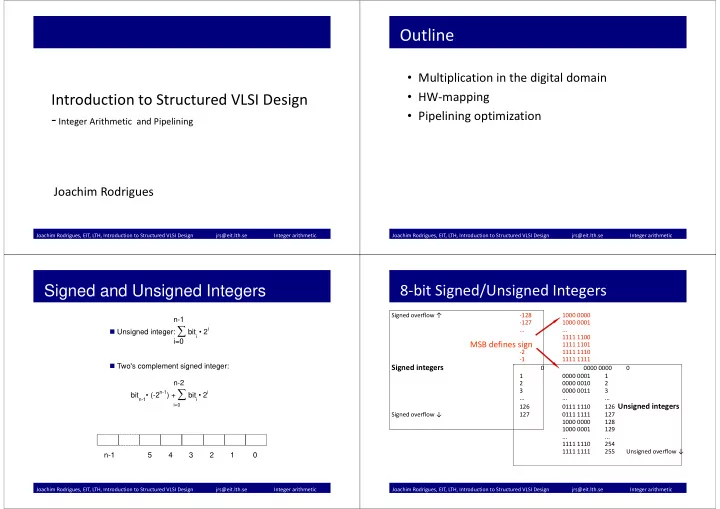
n-1 Unsigned integer: ∑ biti • 2i i=0 Two's complement signed integer: n-2 bitn-1• (-2n-1) + ∑ biti • 2i

i=0

n-1 5 4 3 2 1 0

Signed and Unsigned Integers

Joachim Rodrigues, EIT, LTH, Introduction to Structured VLSI Design jrs@eit.lth.se Integer arithmetic

Signed overflow ↑ ‐128 1000 0000 ‐127 1000 0001 ... ... 1111 1100 1111 1101 ‐2 1111 1110 ‐1 1111 1111

Signed integers

0000 0000 1 0000 0001 1 2 0000 0010 2 3 0000 0011 3 ... ... ... 126 0111 1110 126 Unsigned integers Signed overflow ↓ 127 0111 1111 127 1000 0000 128 1000 0001 129 ... ... 1111 1110 254 1111 1111 255 Unsigned overflow ↓

8‐bit Signed/Unsigned Integers

MSB defines sign

slide-2
SLIDE 2

Joachim Rodrigues, EIT, LTH, Introduction to Structured VLSI Design jrs@eit.lth.se Integer arithmetic

A0 B0 S0 C1 A1 B1 S1 C2 Cn‐1 An‐1 Bn‐1 Sn‐1 Cn C0 = 0 ...

The HW for sum/difference (S) doesn't care about signed/unsigned

Unsigned overflow = Carry‐out & add OR no carry-out & subtract ⇔ Unsigned overflow Signed overflow = Cn ⊕ Cn‐1 True sign = Sn‐1 ⊕ signed overflow = (An‐1 ⊕ Bn‐1 ⊕ Cn‐1) ⊕ (Cn ⊕ Cn‐1) = An‐1 ⊕ Bn‐1 ⊕ Cn

Add/Subtract

+ + +

Joachim Rodrigues, EIT, LTH, Introduction to Structured VLSI Design jrs@eit.lth.se Integer arithmetic

Unsigned Overflow Examples

10+6 = 16, outside [0..15] 1010 +0110 C4=1 0000 Cn = C4 = 1 & add ⇔ Unsigned overflow Carry-out & add ⇔ Unsigned overflow 7-10 = -3, outside [0..15] 0111

  • 1010

same as 0111 0101 + 1 C4=0 1101 Cn = C4 = 0 & subtract ⇔ Unsigned overflow No carry-out & subtract ⇔ Unsigned overflow

Joachim Rodrigues, EIT, LTH, Introduction to Structured VLSI Design jrs@eit.lth.se Integer arithmetic

Signed Overflow Example

6+7 = 13, outside [-8..7] 0110 +0111 C4=0 1101 Cn ⊕ Cn-1 = C4 ⊕ C3 = 0 ⊕ 1 = 1 ⇔ Carry-outs different ⇔ Signed overflow Sn-1 ⊕ signed overflow = An-1 ⊕ Bn-1 ⊕ Cn = A3 ⊕ B3 ⊕ C4 = 0 ⊕ 0 ⊕ 0 = 0 ⇔ True sign = Positive/zero

C3 = 1

Joachim Rodrigues, EIT, LTH, Introduction to Structured VLSI Design jrs@eit.lth.se Integer arithmetic

Product = Multiplicand * Multiplier log (product) = log (multiplicand) + log (multiplier)

Width of product is (worst‐case) sum of widths of factors May overflow if single length product register is used

Paper‐and‐pencil method

Conditional add (controlled by bits of multiplier) and shift Partial product progressively develops into product 1 product bit/cycle

Unsigned and signed multiplication

Signs require extra attention

Sequential, combinational or pipelined implementation

Tradeoff between hardware resources, throughput, latency, power

Multiplication

slide-3
SLIDE 3

Joachim Rodrigues, EIT, LTH, Introduction to Structured VLSI Design jrs@eit.lth.se Integer arithmetic

Example: 1011 * 1110 0000 (*0 = zero) +1011. (*1 = copy) +1011.. (*1 = copy) +1011... (*1 = copy) 10011010

In decimal: 11 * 14 = 154 We will concentrate on unsigned integers for the next few slides !

Multiplying Using Paper and Pencil

Joachim Rodrigues, EIT, LTH, Introduction to Structured VLSI Design jrs@eit.lth.se Integer arithmetic

Multiplicand * Multiplier Partl‐product Partl‐multiplier 1011*1110 0000 1110 0000 (0) +0000 ‐> 00000 111 1011. (1) +1011 . ‐> 010110 11

  • 1011. .

(1) +1011 . . ‐> 1000010 1

  • 1011. . .

(1) +1011 . . . 10011010 10011010

Partial prod uct, part.mul. Multiplicand

0: add zero, 1: add multiplicand Shifting in carry‐out prevents overflow

... more Paper and Pencil

Disadvantage: 2n‐bit ALU Advantage: n‐bit ALU LSB ”controls” whether to add ”0” or multiplicand to partial product

Joachim Rodrigues, EIT, LTH, Introduction to Structured VLSI Design jrs@eit.lth.se Integer arithmetic

Multiplicand Multiplier

bit 0

2n‐bit reg. n‐bit reg.

  • Seq. Multiplication, Initialize

Load Load Load Load

Add Cn

Control signal Joachim Rodrigues, EIT, LTH, Introduction to Structured VLSI Design jrs@eit.lth.se Integer arithmetic

Multiplicand Partial product

Partial multiplier Cn Conditional add bit 0

Repeat step n times

2n‐bit reg.

x

  • Seq. Multiplication, Step

Shift right

n‐bit reg.

Cn Add

slide-4
SLIDE 4

Joachim Rodrigues, EIT, LTH, Introduction to Structured VLSI Design jrs@eit.lth.se Integer arithmetic

Multiplicand Product

bit 0

2n‐bit reg.

  • Seq. Multiplication, Result

n‐bit reg.

Cn Add

  • ne partial product per clock cycle => very slow

Joachim Rodrigues, EIT, LTH, Introduction to Structured VLSI Design jrs@eit.lth.se Integer arithmetic

Either transform to multiply of non‐negative integers:

  • 1. Record signs and negate any negative factors.
  • 2. Perform unsigned multiplication.
  • 3. Negate product if signs above differ.

Or directly perform signed multiplication:

  • 1. Take into account the sign bit of multiplicand by

shifting in true sign bits rather than carry‐outs, i.e. An‐1 ⊕ Bn‐1 ⊕ Cn rather than Cn.

  • 2. Take into account the sign bit of multiplier by

doing a conditional subtract rather than a conditional add during the last iteration.

Don't forget ... Signed Multiplication

Joachim Rodrigues, EIT, LTH, Introduction to Structured VLSI Design jrs@eit.lth.se Integer arithmetic

Multiplicand

Partial multiplier True sign Conditional add for iteration 1.. n‐1, conditional subtract for iteration n bit 0

2n‐bit reg. True sign = An‐1 ⊕ Bn‐1 ⊕ Cn

Repeat step n times

Partial product

  • Seq. signed multiplication, step

Add/ sub

x

n‐bit reg.

True sign

Shift right Joachim Rodrigues, EIT, LTH, Introduction to Structured VLSI Design jrs@eit.lth.se Integer arithmetic

As a designer you need to assure that division with a small constant is accomplished by a number of shifts and adds

Some numerical examples: *2 (*102): multiplicand << 1 *3 (*112): multiplicand << 1 + multiplicand *4 (*1002): multiplicand << 2 *5 (*1012): multiplicand << 2 + multiplicand *255 (*111111112): multiplicand << 8 – multiplicand

Multiplication by a Constant

slide-5
SLIDE 5

Joachim Rodrigues, EIT, LTH, Introduction to Structured VLSI Design jrs@eit.lth.se Integer arithmetic

Mp1*Mc Mp0*Mc Mp2*Mc P1 P0 P2 Pn‐1 P2n‐2..n P2n‐1 Mpn‐1*Mc Unrolling loop lowers latency when compared to sequential add‐and‐shift at the expense

  • f much more hardware

n x n multiplication requires n‐1 n‐bit adders tsaved_latency = n*(tclk‐out+tset‐up)

String of n‐bit Adders

Joachim Rodrigues, EIT, LTH, Introduction to Structured VLSI Design jrs@eit.lth.se Integer arithmetic

Significantly reduced delays for multi‐input adders Full‐adders with clever interconnect Sum and carries fed separately to adder at next level Carries drawn diagonally, sums drawn vertically Typically, a final (carry‐propagate) adder assimilates the carries

+ + + +

A0,0 B0,0 C0,0 C1,0 B0,1 A0,1 S2,1 S2,0 S1,0 C2,2 A1,1 A1,0 C2,1 C0,1 C1,2 S1,1 C1,1

+ +

B0,2 A0,2 S2,2 C2,3 A1,2 C0,2 C1,3 S1,2

CSA0 CSA1

Carry‐save Adders in Multipliers

Joachim Rodrigues, EIT, LTH, Introduction to Structured VLSI Design jrs@eit.lth.se Integer arithmetic

6 x 6 Parallel Array Multiplier

Joachim Rodrigues, EIT, LTH, Introduction to Structured VLSI Design jrs@eit.lth.se Integer arithmetic

+

MP1,0 MP0,1

+ +

MP1,1 MP0,2 MP2,0

+ +

MP1,2 MP0,3 MP2,1

+

MP3,0

+

MP2,2

+

MP3,1

+

MP3,2 MP0,0 MP1,3 MP2,3 MP3,3 P7 P6 P5 P4 P3 P2 P1 P0 MPi, j = Multiplieri AND Multiplicandj

Pipeline registers Pipeline registers Pipeline registers

Carry‐propagate adder

... Pipelined Version

slide-6
SLIDE 6

Joachim Rodrigues, EIT, LTH, Introduction to Structured VLSI Design jrs@eit.lth.se Integer arithmetic

The sequential shift‐and‐add algorithm corresponds to a for‐loop that may be implemented by:

a state machine or instructions (low‐end microcontrollers)

The sequential algorithm may be unrolled and implemented as a deep combinational circuit:

String of n‐bit adders and AND‐gates, or Carry‐save adders, AND‐gates, and final (n‐1)‐bit adder

Advantage: low latency Disadvantage: more hardware The deep combinational circuit may be pipelined Advantage: very high throughput Disadvantages: pipeline latency, more hardware, and higher power

Sequential, Combinational, and Pipelined

Joachim Rodrigues, EIT, LTH, Introduction to Structured VLSI Design jrs@eit.lth.se Integer arithmetic

Pipelining

Joachim Rodrigues, EIT, LTH, Introduction to Structured VLSI Design jrs@eit.lth.se Integer arithmetic

Laundry process

Joachim Rodrigues, Informatik og Matematisk Modellering, jnr@imm.dtu.dk

  • Non‐pipelined:

– Delay: 60 min – Throughput 1/60 load per min

  • Pipelined:

– Delay: 60 min – Throughput k/(40+k*20) load per min about 1/20 when k is large – Throughput 3 times better than non‐pipelined

Comparison

slide-7
SLIDE 7

Joachim Rodrigues, EIT, LTH, Introduction to Structured VLSI Design jrs@eit.lth.se Integer arithmetic

Pipelined combinational circuit

Joachim Rodrigues, EIT, LTH, Introduction to Structured VLSI Design jrs@eit.lth.se Integer arithmetic

Adding pipeline to a comb circuit

  • Candidate circuit for pipeline:

– enough input data to feed the pipelined circuit – throughput is a main performance criterion – comb circuit can be divided into stages with similar propagation delays – propagation delay of a stage is much larger than the setup time and the clock‐to‐q delay of the register.

Joachim Rodrigues, Informatik og Matematisk Modellering, jnr@imm.dtu.dk

Exercise (15 min)

  • Pipeline two 4‐bit adders which

are connected in series. The FFs are ideal(tsetup= tclk‐>Q=0) tpA= 400 ps. The carry out of the 2nd adder can be ignored. How many pipeline stages? Where do you put the FFs? What’s the gain in throughput? How many FFs are required?

FA FA FA FA FA FA FA FA a0 a1 a2 a3 b0 b1 b2 b3 s0p s1p s2p s3p c0 c1 c2 c3 s0 s1 s2 s3 c3

Joachim Rodrigues, EIT, LTH, Introduction to Structured VLSI Design jrs@eit.lth.se Integer arithmetic

– Derive the block diagram of the original combinational circuit and arrange the circuit as a cascading chain – Identify the major components and estimate the relative propagation delays of these components – Divide the chain into stages of similar propagation delays – Identify the signals that cross the boundary of the chain – Insert registers for these signals in the boundary.

Recipe

slide-8
SLIDE 8

Joachim Rodrigues, EIT, LTH, Introduction to Structured VLSI Design jrs@eit.lth.se Integer arithmetic

Datapath

  • RTL description is characterized by registers in a design, and

the combinational logic inbetween.

  • This can be illustrated by a "register and cloud" diagram .
  • Registers and the combinational logic are described

separately in two different processes.

Joachim Rodrigues, EIT, LTH, Introduction to Structured VLSI Design jrs@eit.lth.se Integer arithmetic

Datapath‐Sequential part

architecture SPLIT of DATAPATH is signal X1, Y1, X2, Y2 : ... begin seq : process (CLK) begin if (CLK'event and CLK = '1') then X1 <= Y0; X2 <= Y1; X3 <= Y2; end if; end process;

Joachim Rodrigues, EIT, LTH, Introduction to Structured VLSI Design jrs@eit.lth.se Integer arithmetic

Datapath‐Combinatorial part

LOGIC : process (X1, X2) begin

  • F(X1) and G(X2) can be replaced with the code
  • implementing the desired combinational logic
  • or appropriate functions must be defined.

Y1 <= F(X1); Y2 <= G(X2); end process; end SPLIT; Do not constraint the synhtesis tool by splitting operations, e.g., y1=x1+x12.

Joachim Rodrigues, EIT, LTH, Introduction to Structured VLSI Design jrs@eit.lth.se Integer arithmetic

Pipelining

  • The instructions on the preceeding slides introduced

pipelining of the DP.

  • The critical path is reduced from F(X1)+ G(X2) to the

either F(X1) or G(X2).

slide-9
SLIDE 9

Joachim Rodrigues, EIT, LTH, Introduction to Structured VLSI Design jrs@eit.lth.se Integer arithmetic