Outline Vertex Decimation Algorithms Introduction Taxonomy - - PowerPoint PPT Presentation

outline
SMART_READER_LITE
LIVE PREVIEW

Outline Vertex Decimation Algorithms Introduction Taxonomy - - PowerPoint PPT Presentation

Outline Vertex Decimation Algorithms Introduction Taxonomy Overview Decimation of Triangle Meshes Error Measures Results Extensions Modifying Topology Progressive Meshes Will Schroeder


slide-1
SLIDE 1
  • Decimation of Triangle Meshes

Will Schroeder GE Corporate R&D Schenectady, NY

  • Vertex Decimation Algorithms

– Introduction – Taxonomy – Overview – Error Measures – Results

  • Extensions

– Modifying Topology – Progressive Meshes – Results

  • Industrial Application

– Scientific Visualization – Interactive Visualization – Terrain – Digitized Surfaces

Outline

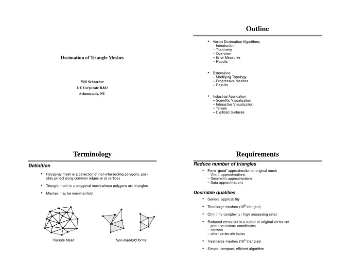
Triangle Mesh Non-manifold forms

  • Polygonal mesh is a collection of non-intersecting polygons, pos-

sibly joined along common edges or at vertices

  • Triangle mesh is a polygonal mesh whose polygons are triangles
  • Meshes may be non-manifold

Terminology

Definition

  • Form “good” approximation to original mesh

– Visual approximations – Geometric approximations – Data approximations

Requirements

Reduce number of triangles Desirable qualities

  • General applicability
  • Treat large meshes (106 triangles)
  • O(n) time complexity / high processing rates
  • Reduced vertex set is a subset of original vertex set

– preserve texture coordinates – normals – other vertex attributes

  • Treat large meshes (106 triangles)
  • Simple, compact, efficient algorithm
slide-2
SLIDE 2
  • Laser range finders
  • 3D coordinate mapping

Data Sources

Digitizers:

  • Satellite
  • Radar Mapping
  • Sonar

Data Sources

Terrain:

  • Iso-Surface Generation
  • Geometry Extraction Techniques
  • Glyph Generation

Data Sources

Visualization:

  • Stereo Lithography
  • Graphics Representations
  • Mesh Generation / Tessellation

Data Sources

Modeling / Tessellation:

slide-3
SLIDE 3
  • Tessellation algorithms -> 104 polygons
  • Digital elevation data -> 105 to 107 polygons
  • 3D Digitizers -> 105 to 106 polygons
  • Iso-surface generation -> 106 triangles

Motivation

Triangle meshes are large:

  • Slower rendering speeds
  • Large memory requirements
  • More expensive analysis

Large meshes mean

Taxonomy of Methods

Topology Preserving Topology Modifying Vertex Subset Resample

Topology Preserving Original topology of mesh maintained Topology Modifying Original topology of mesh may be modified Vertex Subset Set of reduced vertices is a subset of original vertices. Resample Reduced vertices do not belong to original set

  • f vertices.

Decimation Geometric Optimization Soucy, vertex removal tech- niques Rossignac & Borrel Progressive Decimation Visual polygons Bounding Hulls Implicit Modeling Turk Hoppe Multiresolution analysis

  • Visible polygons
  • Discard polygons not visible during viewing
  • Bounding Hulls
  • Convex hulls (Delaunay triangulations. etc).
  • Shrink-wrapped polygonal surfaces
  • Bounding boxes; close fit bounding polyhedra
  • Implicit modeling
  • Voxelize based on distance function
  • Use low-resolution volume
  • Extract iso-surface of distance value

Simple Methods

  • Characterize local topology and geometry
  • Evaluate decimation criterion
  • If criterion satisfied, remove vertices and associated triangles
  • Triangulate resulting hole

Decimation Algorithm

Iterate over set of vertices; for each vertex:

  • Fast O(n) time complexity
  • Creates simplified mesh with subset of vertices
  • Topology Preserved
  • Flexible framework for different error measure / triangulation

Features

slide-4
SLIDE 4
  • Three basic steps (repeated for each vertex)

Decimation

Schroeder, Zarge, Lorensen, Proc. Siggraph ‘92.

Evaluate local topol-

  • gy / geometry

Triangulate Delete Vertex

  • Look for sharp corners / edges
  • Look for non-manifold cases
  • Evaluate decimation criterion:

– vertex distance to plane (if interior vertex) – vertex distance to line (if boundary vertex or if sharp edge)

  • O(n) for each pass

Decimation

Evaluate local topology / geometry:

  • Vertex is not complex
  • Vertex is not classified as “corner” vertex
  • Vertex meets decimation criterion (i.e., distance to plane for inte-

rior vertices, distance to edge for boundary vertices or for verti- ces on sharp edge)

  • Triangulation, including constraints on aspect ratio, is possible.

Decimation

Delete vertex under following conditions:

  • Use 3D recursive loop splitting
  • Polygons creased with sharp edge are triangulated along edge
  • Aspect ratio controlled to insure good retriangulations

Decimation

Triangulation:

slide-5
SLIDE 5
  • Simple vertex

– complete cycle of triangles – each triangle edge used twice

  • Boundary vertex

– semi-cycle of triangles – boundary edges used once – interior edges used twice

  • Complex vertex

– non-manifold

Vertex Classification

Simple Boundary Complex

  • Identify feature edges (specified dihedral angle)
  • Interior edge vertex -> 2 feature edges
  • Corner vertex -> 1 or 3 or more feature edges

Simple Vertex Classification

Simple vertices are further classified based on geometry (i.e., evaluation of feature edges)

Simple Vertex Classification

Simple Interior Edge Corner

  • Distance to plane

– simple vertices

  • Distance to line

– boundary vertices – interior edge vertices

  • Corner and complex vertices not removed

Decimation Criterion

Vertex removal based on decimation criteria d d

  • Distance to “average” plane

– simple vertices

  • Distance to line

– boundary vertices – interior edge vertices

slide-6
SLIDE 6
  • Hole is star-shaped
  • Hole is generally non-planar
  • Use recursive 3D loop splitting process
  • Splits controlled by aspect ratio (maximum vertex distance from

split line) / (length of split line) -> choose large values.

Triangulation

Vertex removal creates hole to be patched

Split plane Split line

  • Not possible to find split line
  • Aspect ratio not satisfied
  • Collapsing simple volumes
  • Collapsing tunnels

Triangulation

Triangulation Failure:

Non-manifold attachments from tunnels

  • Vertex list

– x,y,z coordinates

  • Triangle list

– 3 defining vertices

  • Vertex use list

– triangles using vertex (see included paper)

Data Structure

Data structure is critical to algorithm efficiency

Triangle Vertex Dynamic Fixed

  • Medical
  • Terrain
  • Geometric Modeling
  • Laser Digitizer

Results

slide-7
SLIDE 7
  • Distance measures
  • Surface Area
  • Removal Volume
  • Energy Functions
  • Hausdorff Distance

Characterizing Algorithms

Error Measures:

  • Absolute
  • Relative

Error Measures

Distance Measures: d d

  • Distance to “average” plane
  • Distance to line
  • Total area of mesh before and after reduction
  • Can be computed incrementally (in most cases)

Error Measures

Surface Area:

Si Si

1 +

∆Ei

1 +

Si

1 +

Si – =

  • Volume enclosed by initial and reduced mesh.
  • Can be computed incrementally in some cases.

Error Measures

Removal Volume:

Initial mesh Reduced mesh

slide-8
SLIDE 8
  • Combinations of error functions, representational functions, and

terms to guarantee minimum value.

  • Error functions could include distance, surface area, and/or vol-

ume functions, as well as constraints on triangle shape.

Error Measures

Energy Functions:

  • The maximum distance between two distance measures:

– Distance of points in simplified mesh to original mesh – Distance of points in original mesh to simplified mesh

  • Symmetric
  • Klein, Liebich, Strasser, Mesh Reduction with Error Control,
  • Proc. of Visualization ‘96.

Error Measures

Hausdorff Distance

  • Topology Constraints

– Genus Preservation – Manifold vs. Non-Manifold Topology

  • Progressive Meshes

– Smooth transitions between reduction level – Encodable, compact operations on the mesh

Extensions To Decimation

Going Beyond These Limitations

  • Collapsing holes

Topological Constraints

Genus Preservation

a) Original model 1,132 triangles b) Topology unchanged 43 triangles c) Topology modified (2 triangles)

slide-9
SLIDE 9
  • Tunnel collapse can create non-manifold topology

Topological Constraints

Genus Preservation

  • Result is two or more manifold pieces

Splitting Mesh

Non-manifold Vertices Can be Split

  • Along sharp edges
  • Triangulate complex regions
  • Recovering from mesh degeneracies

Extending Splitting

Use Splitting To Address Other Cases

Split Operations

A Family of Operations

Other types Interior Edge Corner Non-manifold

slide-10
SLIDE 10
  • Smooth transitions between reduction level
  • Compact, encodable operations for efficient storage and

transmission

  • Original implementation was topology preserving edge collapse /

edge split

Progressive Meshes

Hoppe Siggraph ‘96

vr vl vt vs

Collapse Split

vl vr vt

  • Vertex split - create identical vertex and update topology of mesh
  • Vertex merge - merge coincident vertices

Topology Modifying Operations

Progressive operations extended

vr vl vs

Split Merge

vl vr vt vs

  • Triangulation operation is altered to use edge collapse
  • Mesh splitting is performed to resolve non-manifold / complex

conditions

  • Progressive operations for efficient storage and transmission;

and smooth playback

  • Guaranteed reduction level

Progressive Decimation Algorithm

Extend decimation for topological modification

Results

Progressive decimation

a) Original model 2,624 triangles b) Shortly after splitting 157 triangles c) Final model 4 triangles

slide-11
SLIDE 11

Results

Progressive decimation

a) Original model 11,006 triangles b) Reduction 50%, 5,518 triangles c) Just after mesh splitting d) Reduction 90%, 1,100 triangles e) Reduction 95%, 550 triangles f) Reduction 98%, 220 triangles

Results

Progressive decimation

a) Original model 314,39 triangles b) Shortly before splitting 187,449 triangles, reduc- tion 40.4% c) 50% reduction, 157,196 triangles d) 75% reduction, 78,598 triangles e) 90% reduction, 31,439 triangles c) 95% reduction, 15,719 triangles

Results

Progressive decimation

a) Original model 1,683,472 triangles b) Close-up of edges showing holes leading to interior c) 75% reduction, 420,867triangles d) Shortly before splitting 134,120 triangles, e) 95% reduction, 84,173 triangles f) 99.5% reduction, 8,417 triangles

  • Nearly 100,000 triangles / elapsed minute rate
  • Can process 100 million triangles / day
  • Trade-off between fidelity and speed

Figure 1. Results for five different meshes. Times shown are elapsed seconds. Number of edge collapses and vertex splits are also shown. The rate is the maximum number of triangles eliminated per elapsed minute.

Model Number Triangles Reduction 0.5 Reduction 0.75 Reduction 0.90 Reduction 1.00 Rate

time collapses splits time collapses splits time collapses splits time collapses splits

Shell 1132 0.46 319 0.68 494 0.70 557 0.76 648 89,368 Plate 2624 1.07 656 1.41 984 1.68 1228 169 1.73 1457 221 91,006 Heat Ex. 11,006 3.27 2759 4.42 4139 5.36 5447 914 5.86 6355 1160 112,689 Turbine 314,393 158 98,401 43,011 202 157,877 69,019 229 202,702 83,214 241 232,281 88,184 78,272 Blade 1,683,472 747 421,042 825 631,606 914 758,056 1042 852,743 24,501 96,937

Results

Progressive Decimation

slide-12
SLIDE 12
  • Isosurface from industrial CT: 1.68 million triangles

Industrial Application

Scientific Visualization

  • Isosurface from medical CT:90% reduction
  • Datasets on the order of 100 million triangles
  • Need to process data within a single day

Industrial Application

Interactive Visualization

  • 95% reduction with texture

Industrial Application

Digitized Surfaces