outline Background JPL MER example Reliable State Machines JPL - - PDF document

outline
SMART_READER_LITE
LIVE PREVIEW

outline Background JPL MER example Reliable State Machines JPL - - PDF document

outline Background JPL MER example Reliable State Machines JPL FPGA/ASIC Process Procedure Guidelines Dr. Gary R Burke State machines Traditional California Institute of Technology Highly Reliable Jet


slide-1
SLIDE 1

1

10/14/2005 Caltech 1

Reliable State Machines

  • Dr. Gary R Burke

California Institute of Technology Jet Propulsion Laboratory

10/14/2005 Caltech 2

  • utline
  • Background

– JPL MER example

  • JPL FPGA/ASIC Process

– Procedure – Guidelines

  • State machines

– Traditional – Highly Reliable – Comparison

10/14/2005 Caltech 3 10/14/2005 Caltech 4 10/14/2005 Caltech 5 10/14/2005 Caltech 6
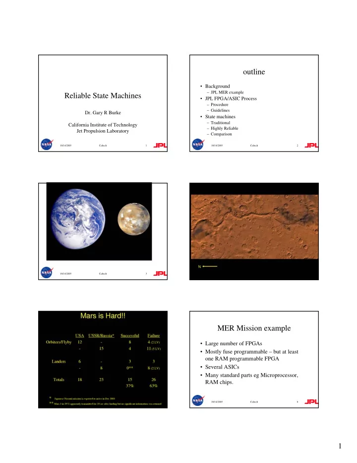
MER Mission example

  • Large number of FPGAs
  • Mostly fuse programmable – but at least
  • ne RAM programmable FPGA
  • Several ASICs
  • Many standard parts eg Microprocessor,

RAM chips.

slide-2
SLIDE 2

2

10/14/2005 Caltech 7 10/14/2005 Caltech 8 10/14/2005 Caltech 9 10/14/2005 Caltech 10 10/14/2005 Caltech 11 10/14/2005 Caltech 12

slide-3
SLIDE 3

3

10/14/2005 Caltech 13 10/14/2005 Caltech 14

FPGA/ASIC Process

  • JPL needs to ensure design process is sound
  • A bug in an FPGA/ASIC can halt a billion dollar

mission

  • Tight schedules can result in inadequate testing
  • Inadequate version control can result in the wrong

code

  • First Pass success important for ASIC design

10/14/2005 Caltech 15

FPGA/ASIC Process

  • To ensure a quality product:
  • Requirements are correct and do not change
  • Specification is complete
  • Design will meet the specification and

requirements

  • Testing has covered all possible cases

10/14/2005 Caltech 16

FPGA/ASIC Process

  • Peer reviews by experts to check the design

and design approach

  • Formal Reviews to ensure design process is

adequate, and to sign off on the design

  • Documentation for review and archiving
  • Check-lists to ensure all problems are fixed

10/14/2005 Caltech 17

FPGA/ASIC Process

  • Configuration Management to ensure

correct versions are used

  • Verification Matrix – which documents all

testing

  • Checking tools e.g. Lint, DRC; all errors,

and warnings documented

10/14/2005 Caltech 18

ASIC PROCESS

Specification: HDL Design: Structural design: Physical Design: Complete Layout:: IDR Review PDR Review CDR Review STA RT ASIC Design Process GRB - 2/1/04 Inputs Level 5 Requirements
  • utputs

Create Specification. Preliminary design. Test Approach. ASIC/FPGA/ package selection. Configuration management Review plan Select Foundry Partition Design Specify IPs FT approach process Preliminary Specification CM plan Test approach Conceptual Design & Requiremen ts Review Is ASIC ready to procede with detailed design? RTL code, Test Plan Updated Specification RTL Design; RTL simulation DFT;simulation coverage V test bench & modeling Trial Synthesis Trial Timing analysis Trial testability anal. Test Plan Initial Firmware design SEU mitigation plan Fault tolerant plan Lint verification pinout defined code walkthrough PDR Is ASIC Ready to procede with structural design? Synthesis Timing analysis testability Prototype; ATPG Vendor software Gate level verification Firmware design Test vectors TV coverage Trial P&R Prototype FPGA Formal Verification Structural code Test Vectors Structural Design Peer Review and Sign-off Physical Design: Place and Route Timing analysis BA Update Prototype Test Vectors BA Vendor software BA Gate level verification BA Test vectors Layout netlist V-matrix Physical Design Peer review and sign-off Chip layout Complete Layout:: Chip integration DRC LVS ERC CDR Review: Is ASIC ready for fabrication? CDR Checklist Firmw are Design: A nalog Circuit Design: Analog Layout Design: Firmw are Compilation Proto Board Test Proto Board Design Structural Design sign-of f Physical Design sign-off Preliminary Specification CM plan Test approach RTL code, Test Plan Updated Specification Structural code Test Vectors chip fabrica tion

slide-4
SLIDE 4

4

10/14/2005 Caltech 19

FPGA PROCESS

Specification: HDL Design: FPGA Prototype design: FPGA Final Build IDR Review PDR Review CDR START FPGA Design Process GRB - 2/1/04 Inputs Level 5 Requirements
  • utputs

Create Specification. Implementation Partition and Test Approach. FPGA device and package selection. Configuration management Schedule with Plan for Reviews Specify IPs FT approach process Preliminary Specification CM plan Test approach Conceptual Design & Requiremen ts Review Is FPGA ready to procede with detailed design? RTL code, Test Plan Updated Specification HDL Design; HDL simulation DFT;simulation coverage V test bench & modeling Trial Synthesis Trial Timing analysis Test Plan Initial Firmware design SEU mitigation plan Fault tolerant plan Lint verification pinout defined code walkthrough prot-board design Is FPGA Ready to procede with synthesis? Synthesis Timing analysis testability Prototype FPGA software Gate level verification Firmware design Test vectors TV coverage Prototype FPGA Configuration code Test Vectors Physical Design: Place and Route Timing analysis Update Prototype Test Vectors Vendor software System Test Verification matrix; Test vectors CDR Review: Is flight FPGA ready for personalizat ion? CDR Checklist Firmw are Design: Proto-Board Test Firmw are V erification Prot-board design FPGA fuse programming Preliminary Specification CM plan Test approach RTL code, Test Plan Updated Specification Configuration code Test Vectors

10/14/2005 Caltech 20

Guidelines

  • Define set of rules for HDL design
  • Reduce ambiguity
  • Clarify design to be easily checked and

reviewed

  • Implement most reliable design techniques

10/14/2005 Caltech 21

Fault Tolerant State Machines

  • The state machine needs to be tolerant of

single event upsets

  • State machine should not hang
  • State machine should always be in a defined

state

  • No asynchronous inputs to state machine
  • Default state must be specified

10/14/2005 Caltech 22

State Machines

  • A state machine is a sequential machine that when

built into an FPGA or ASIC controls the sequencing of actions in the digital logic

  • The current state of a machine is held in a state

register which is updated on a clock

  • The next value of the state register (next state) is

derived from the current state and the inputs

  • Outputs from the state machine are decoded from

the state register and can also be combined with the inputs

10/14/2005 Caltech 23

State-Machine (SM) Encoding

  • Each distinct state of the SM is represented

by a unique code

  • The allocation of these binary codes to

states is the Encoding

  • The simplest encoding is Binary
  • In Binary encoding each state is given the

next available binary number in sequence.

10/14/2005 Caltech 24

Other SM Encoding

  • 1-hot encoding

– The number of bits in the code is equal to the number

  • f states. Each encoded state has just 1 bit in the

encoded word set to a 1 (the rest are 0) – The advantage is that when optimized for non-reliable use, the amount of logic needed is less than Binary encoding, and it can be faster. One bit change with a SEU will result in a bad code which can be detected. – The disadvantage is the increased number of bits results in more flip/flops and therefore more targets for SEUs. The SEU advantage is lost when the 1-hot encoding is

  • ptimized.
slide-5
SLIDE 5

5

10/14/2005 Caltech 25

Other SM Encoding- cont

  • Grey-code

– Similar to binary encoding, except the codes are chosen so that in the main state-machine sequence only 1 bit changes at a time – No major advantage over binary with this code. Decoded outputs from the state register can make use of the nature of the encoding to simplify producing a glitch free output.

10/14/2005 Caltech 26

Other SM Encoding- cont

  • H2-code

– This variation on Binary encoding uses one extra bit to ensure all codes are separated by a Hamming distance of 2. That is, it will take 2 changes in the state register to reach another known state. – The advantage is that it has less bits and so less SEU targets than 1-hot, but retains the fault tolerance of the un-optimized 1-hot encoding.

10/14/2005 Caltech 27

Other SM Encoding- cont

  • H3-code

– This extension on H2 encoding uses additional bits to ensure all codes are separated by a Hamming distance

  • f 3. That is, it will take 3 changes in the state register

to reach another known state. – The advantage is that the SM can be designed such that a single change in the state register has no effect on the state. – The disadvantage is that it requires more logic to implement

10/14/2005 Caltech 28

Synthesis

  • To check the overhead of each of the state

machines, they were individually synthesized

  • Finite state machine optimization is turned off
  • A clock frequency of 50 MHz is used
  • Target device is a Xilinx Spartan 2, speed grade 6
  • Error injection circuitry is not included

10/14/2005 Caltech 29

Synthesis Results

State Machine Size # Slice Flip Flops # of 4 input LUTs Clock Period (ns) Max Synthesized Frequency (MHz) Minimum Period (ns) 4 3 8 20 226.6 4.4 8 4 22 20 133.5 7.5 12 5 41 20 124.5 8.0 16 5 49 20 117.8 8.5 24 6 84 20 91.5 10.9 32 6 107 20 87.3 11.5 4 5 15 20 162.8 6.1 8 6 42 20 117.4 8.5 12 7 55 20 105.0 9.5 16 7 71 20 102.6 9.8 24 9 91 20 88.7 11.3 32 9 137 20 83.5 12.0 Hamming 2 Hamming 3 State Machine Size # Slice Flip Flops # of 4 input LUTs Clock Period (ns) Max Synthesized Frequency (MHz) Minimum Period (ns) 4 2 7 20 272.1 3.7 8 3 15 20 178.8 5.6 12 4 25 20 129.6 7.7 16 4 38 20 122.1 8.2 24 5 50 20 109.6 9.1 32 5 96 20 94.5 10.6 4 4 10 20 238.2 4.2 8 8 20 20 194.8 5.1 32 12 31 20 173.0 5.8 16 16 41 20 148.9 6.7 24 24 63 20 148.9 6.7 32 32 237 20 68.6 14.6 Binary One Hot

10/14/2005 Caltech 30

Four Bit State Encoding

4 Bit State Encoding

2 4 3 5 7 10 8 15 3.7 4.2 4.4 6.1 2 4 6 8 10 12 14 16 Binary One Hot Hamming 2 Hamming 3 # of Slice Flip Flops # of Four Input LUTs Clock Period (ns)

slide-6
SLIDE 6

6

10/14/2005 Caltech 31

Eight Bit State Encoding

8 Bit State Encoding 3 8 4 6 15 20 22 15 5.6 5.1 7.5 8.5 5 10 15 20 25 Binary One Hot Hamming 2 Hamming 3 # of Slice Flip Flops # of Four Input LUTs Clock Period (ns)

10/14/2005 Caltech 32

Twelve Bit State Encoding

12 Bit State Encoding

4 12 5 7 25 31 41 55 7.7 5.8 8.0 9.5 10 20 30 40 50 60 Binary States One Hot Hamming 2 Hamming 3 # of Slice Flip Flops # of Four Input LUTs Clock Period (ns)

10/14/2005 Caltech 33

Sixteen Bit State Encoding

16 Bit State Encoding

4 16 5 7 38 41 49 71 8.2 6.7 8.5 9.8 10 20 30 40 50 60 70 80 Binary One Hot Hamming 2 Hamming 3 # of Slice Flip Flops # of Four Input LUTs Clock Period (ns)

10/14/2005 Caltech 34

Twenty-Four Bit State Encoding

24 Bit State Encoding

5 24 6 9 50 91 9.1 6.7 10.9 11.3 63 84 10 20 30 40 50 60 70 80 90 100 Binary One Hot Hamming 2 Hamming 3 # of Slice Flip Flops # of Four Input LUTs Clock Period (ns)

10/14/2005 Caltech 35

Thirty-Two Bit State Encoding

32 Bit State Encoding

5 6 9 96 107 137 14.6 11.5 12.0 32 237 10.6 50 100 150 200 250 Binary One Hot Hamming 2 Hamming 3 # of Slice Flip Flops # of Four Input LUTs Clock Period (ns)

10/14/2005 Caltech 36

Fault Injection Test

  • A test circuit is generated with an example of each

state machine executing the same task, plus a reference state machine

  • The task chosen requires a16-state state machine,

to detect a 16-bit pattern in a serial input stream

  • An error generator injects faults into all state

machines except the reference state machine

slide-7
SLIDE 7

7

10/14/2005 Caltech 37

Error Injection Test Continued

  • The outputs of each state machine are compared to

the reference output

  • A set of counters tallies the comparison outputs
  • 2 types of failure are logged for each state

machine:

– Failure to detect pattern – False detection of pattern (false-positive)

10/14/2005 Caltech 38

Error Injection Test Continued

  • Non-key patterns are 1-bit different from the key pattern,

to increase the likelihood of a false match

  • Error rate can vary, set to 1:199 clocks in example
  • Errors are weighted by distributing them pseudo-randomly
  • ver 16 bits. A state machine with a word size of n,

receives n/16 of the total faults

  • Synchronous fault injection is before the state register
  • Asynchronous fault injection is after the state register
  • All results are from actual implementation of the test

circuits in a Spartan 2 FPGA

10/14/2005 Caltech 39

Error Rate – Synchronous Faults

Synchronous (rate=199) 0.01 0.02 0.03 0.04 0.05 0.06 0.07 0.08 0.09 0.1 Binary 1-Hot H2 H3 errors per pattern single false-pos single double false-pos double

10/14/2005 Caltech 40

Error Rate – Asynchronous Faults

Asynchronous (rate=199) 0.002 0.004 0.006 0.008 0.01 0.012 0.014 0.016 0.018 0.02 Binary 1-Hot H2 H3 errors per pattern single false-pos single double false-pos double

10/14/2005 Caltech 41

Error Rate – Asynchronous Pulse Faults

Pulse (rate=199) 0.002 0.004 0.006 0.008 0.01 0.012 0.014 0.016 0.018 Binary 1-Hot H2 H3 errors per pattern single false-pos single double false-pos double

10/14/2005 Caltech 42

Results: Binary Encoding

  • Lowest resources used
  • Second fastest speed after One Hot

– Fastest for small number of states

  • Second-most sensitive to errors
  • Generates false-positive errors i.e. reports

false pattern matches

slide-8
SLIDE 8

8

10/14/2005 Caltech 43

Results: One Hot Encoding

  • No false-positive errors (single faults)
  • Fastest speed except for small number of states

and large number of states

  • Uses more resources than Binary
  • Inefficient for large number of states
  • Worst fault tolerance of all encoding tested
  • Has 2x the error rate of binary encoding

10/14/2005 Caltech 44

Results: Hamming Distance of 2 (H2) Encoding

  • No false-positive errors (single faults)
  • Better Fault Tolerance than Binary
  • More resources needed than One Hot,

except for large number of states

10/14/2005 Caltech 45

Results: Hamming Distance of 3 (H3) Encoding

  • Zero single-fault errors

– Immune to synchronous and asynchronous errors

  • Lowest double-fault errors
  • Most resources used (*)

~2x binary encoding

  • Slowest speed (*)

(*) Except for large number of states