
SLIDE 1
18TH INTERNATIONAL CONFERENCE ON COMPOSITE MATERIALS
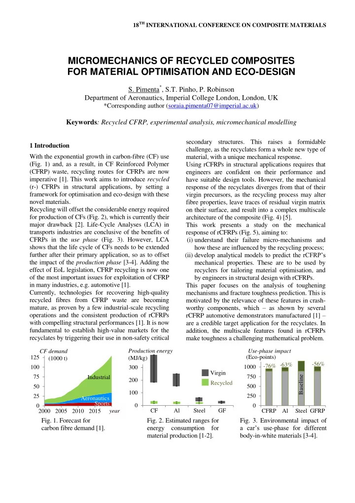
1 Introduction With the exponential growth in carbon-fibre (CF) use (Fig. 1) and, as a result, in CF Reinforced Polymer (CFRP) waste, recycling routes for CFRPs are now imperative [1]. This work aims to introduce recycled (r-) CFRPs in structural applications, by setting a framework for optimisation and eco-design with these novel materials. Recycling will offset the considerable energy required for production of CFs (Fig. 2), which is currently their major drawback [2]. Life-Cycle Analyses (LCA) in transports industries are conclusive of the benefits of CFRPs in the use phase (Fig. 3). However, LCA shows that the life cycle of CFs needs to be extended further after their primary application, so as to offset the impact of the production phase [3-4]. Adding the effect of EoL legislation, CFRP recycling is now one
- f the most important issues for exploitation of CFRP
in many industries, e.g. automotive [1]. Currently, technologies for recovering high-quality recycled fibres from CFRP waste are becoming mature, as proven by a few industrial-scale recycling
- perations and the consistent production of rCFRPs
with compelling structural performances [1]. It is now fundamental to establish high-value markets for the recyclates by triggering their use in non-safety critical secondary structures. This raises a formidable challenge, as the recyclates form a whole new type of material, with a unique mechanical response. Using rCFRPs in structural applications requires that engineers are confident on their performance and have suitable design tools. However, the mechanical response of the recyclates diverges from that of their virgin precursors, as the recycling process may alter fibre properties, leave traces of residual virgin matrix
- n their surface, and result into a complex multiscale
architecture of the composite (Fig. 4) [5]. This work presents a study on the mechanical response of rCFRPs (Fig. 5), aiming to: (i) understand their failure micro-mechanisms and how these are influenced by the recycling process; (ii) develop analytical models to predict the rCFRP’s mechanical properties. These are to be used by recyclers for tailoring material optimisation, and by engineers in structural design with rCFRPs. This paper focuses on the analysis of toughening mechanisms and fracture toughness prediction. This is motivated by the relevance of these features in crash- worthy components, which – as shown by several rCFRP automotive demonstrators manufactured [1] – are a credible target application for the recyclates. In addition, the multiscale features found in rCFRPs make toughness a challenging mathematical problem.
- Fig. 1. Forecast for
carbon fibre demand [1].
- Fig. 2. Estimated ranges for
energy consumption for material production [1-2].
- Fig. 3. Environmental impact of
a car’s use-phase for different body-in-white materials [3-4].
25 50 75 100 125 2000 2005 2010 2015 2020 Aeronautics Sports Industrial CF demand (1000 t) year 100 200 300 CF Al Steel GF Virgin Recycled Production energy (MJ/kg) 250 500 750 1000 1250 CFRP Al Steel GFRP Use-phase impact
- 56%
- 63%
- 76%
Baseline (Eco-points)
MICROMECHANICS OF RECYCLED COMPOSITES FOR MATERIAL OPTIMISATION AND ECO-DESIGN
- S. Pimenta*, S.T. Pinho, P. Robinson