
SLIDE 1
1
1
Memory Testing
2
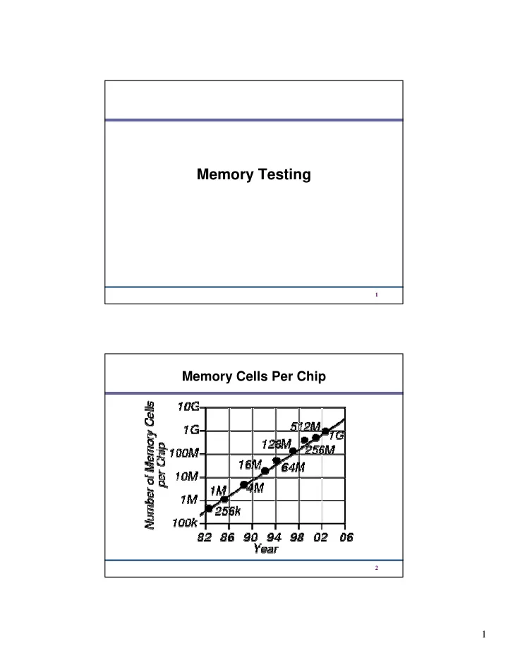
Memory Testing 1 Memory Cells Per Chip 2 1 Test Time in Seconds - - PDF document
Memory Testing 1 Memory Cells Per Chip 2 1 Test Time in Seconds (Memory Size n Bits, Memory Cycle Time 60ns) Size Number of Test Algorithm Operations n 2 n 3/2 n n n X log 2 n 64.5 0.06 1 Mb 1.26 18.3 hr 515.4 4 Mb 0.25
1
2
3
4
5
6
7
8
9
10
11
12
13
14
15
16
17
18
19
20
21
22
23
24
25
26
27
28
29
30
31
32
33
34
35
36
37
38
39
40
41
42
43
44
45
46
49
0000 0001 0010 0011 0100 0101 0110 0111 1000 1001 1010 1011 1100 1101 1110 1111
53
54
55
56
57
58
59