
SLIDE 1
18TH INTERNATIONAL CONFERENCE ON COMPOSITE MATERIALS
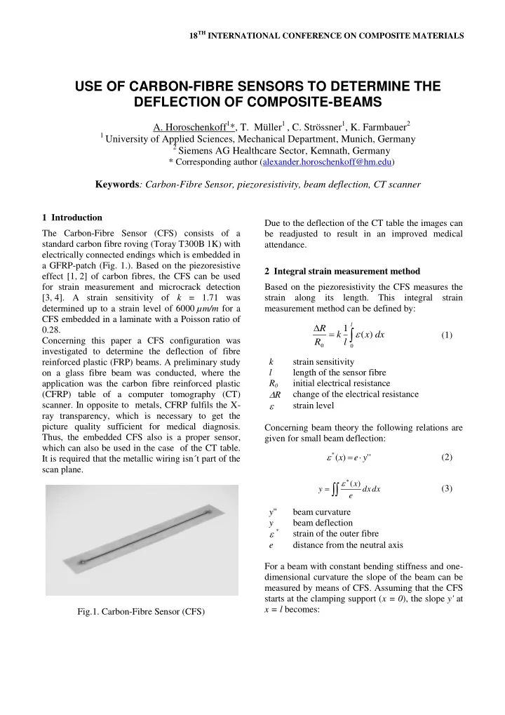
1 Introduction The Carbon-Fibre Sensor (CFS) consists of a standard carbon fibre roving (Toray T300B 1K) with electrically connected endings which is embedded in a GFRP-patch (Fig. 1.). Based on the piezoresistive effect [1, 2] of carbon fibres, the CFS can be used for strain measurement and microcrack detection [3, 4]. A strain sensitivity of k = 1.71 was determined up to a strain level of 6000 µm/m for a CFS embedded in a laminate with a Poisson ratio of 0.28. Concerning this paper a CFS configuration was investigated to determine the deflection of fibre reinforced plastic (FRP) beams. A preliminary study
- n a glass fibre beam was conducted, where the
application was the carbon fibre reinforced plastic (CFRP) table of a computer tomography (CT)
- scanner. In opposite to metals, CFRP fulfils the X-
ray transparency, which is necessary to get the picture quality sufficient for medical diagnosis. Thus, the embedded CFS also is a proper sensor, which can also be used in the case of the CT table. It is required that the metallic wiring isn´t part of the scan plane. Fig.1. Carbon-Fibre Sensor (CFS) Due to the deflection of the CT table the images can be readjusted to result in an improved medical attendance. 2 Integral strain measurement method Based on the piezoresistivity the CFS measures the strain along its length. This integral strain measurement method can be defined by:
dx x l k R R
l
) ( 1
(1) k strain sensitivity l length of the sensor fibre R0 initial electrical resistance R change of the electrical resistance strain level Concerning beam theory the following relations are given for small beam deflection: ' ' ) (
*
y e x (2)
dx dx e x y
) (
(3) y'' beam curvature y beam deflection * strain of the outer fibre e distance from the neutral axis For a beam with constant bending stiffness and one- dimensional curvature the slope of the beam can be measured by means of CFS. Assuming that the CFS starts at the clamping support (x = 0), the slope y' at x = l becomes:
USE OF CARBON-FIBRE SENSORS TO DETERMINE THE DEFLECTION OF COMPOSITE-BEAMS
- A. Horoschenkoff1*, T. Müller1 , C. Strössner1, K. Farmbauer2
1 University of Applied Sciences, Mechanical Department, Munich, Germany 2 Siemens AG Healthcare Sector, Kemnath, Germany