
SLIDE 1
Journal of Environmental Treatment Techniques 2015, Volume 3, Issue 2, Pages: 113-117
113
Investigation and Presentation of the Valuation Type Graphs and Plans to Design Protection System of Soldier Pile Excavation Wall
Mojtaba Askari1, Babak Mansouri2* 1- Department of Civil Engineering, Firoozabad Branch, Islamic Azad University, Firoozabad, Iran 2- Department of Civil Engineering, Meymand Center, Islamic Azad University, Meymand, Iran Received: 08/04/2015 Accepted: 08/06/2015 Published: 30/06/2015
Abstract
In recent years with regard to development of our country different towns and thereby the necessity of special and deep excavations, many wall collapses were observed. The stability of excavation walls can be supplied by various methods depending
- n the conditions of land, depth and wall surrounding live loads. One of these methods is to use Soldier Pile system along with
anchor bolt. The important advantages of this system is the significant reduction of occupied space by soldier structure and the reduction of time and running cost in big projects. Components design of this system depends on various parameters such as soil physical properties, including soil cohesion (C), angle of internal friction (φ), soil bulk density (ϒ) and excavation conditions including excavation height (H), fixed length (D), the amount of live load (ω) and anchor situations. This paper presents wide parametric studies by changing aforementioned parameters and uses Support IT software to analyze different states, type valuations graphs and running plans as the charts used by engineers in rapid designing of this system to stabilize excavation. Key words: Protection system, soldier pile, design protection system
1 Introducing Soldier Pile System1
Soldier pile consists of different materials and profiles and mostly is applied in connection with timbers as ground support system like a continuous wall. In soldier pile elements, H or IPB profiles or shield profiles are used. The materials which are applied between profiles are wooden timbers with metal plates or concrete sections. A part of soil force by timbers and another part by arc phenomena are transported to soldier pile profiles [3]. The method is to excavate speculations in the intended ground margins in certain distances while the depth of these speculations is equal to excavation depth plus fixed length. After excavating these speculations profiles are installed within them then the fixed length which is obtained with calculation is concreted. After running above steps, the excavation operation is ran in steps which in this step anchor bolts are used to control soil if necessary which the necessity of using anchor bolts is specified in calculations. Then wooden timbers or prefabricated concrete panels are installed between the vertical profiles and control them to profiles and anchor-bolts. All of mentioned operations are implemented from top to bottom [2]. Corresponding author: Babak Mansouri, Department of Civil Engineering, Meymand Center, Islamic Azad University, Meymand, Iran.
2 The Advantages of Soldier Pile System
Soldier structure is not in fixed excavation and doesn’t
- ccupy excavation space. 2- The time and cost of running
- peration decreases in big projects. 3- The amount of soil
drift decreases using anchor-bolts. 4- The existing soil is used to control excavation wall. 5- Grouting injection results in the reinforcement of soil physical properties [1].
3 The Methods of System Designing and the Effect of Various Variables:
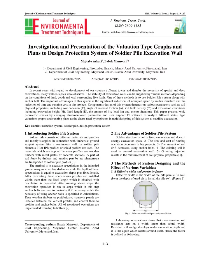
- 3. A Effective width and proximity factor
Effective width is the width of the pile parallel to wall (b) or the depth of used pit to install the pile (w). (Figure 1)
- Fig. 1: Effective width and proximity coefficient
Laboratory observations show that cohesion-less soil resistance acts on a width larger than actual width. Resistant soil wedge develops under excavation depth and it is like a pile which rotates around itself. Hence the factor is defined as following:
Journal web link: http://www.jett.dormaj.com
- J. Environ. Treat. Tech.