introduction
play

Introduction peak limiting current mode control . . . known since - PDF document

Introduction peak limiting current mode control . . . known since 1978, C. W. Deisch, Simple switching control method changes power converter into a current source, Conduction Modes of a Peak Limiting PESC78 [2] Current Mode


  1. Introduction ◮ peak limiting current mode control . . . ◮ known since 1978, C. W. Deisch, “Simple switching control method changes power converter into a current source,” Conduction Modes of a Peak Limiting PESC’78 [2] Current Mode Controlled Buck Converter ◮ revisited many times, e.g. in 2001 [6] and 2011 (!) [7] ◮ still something to say? Predrag Pejović, Marija Glišić ◮ CCM, DCM, stability, D > 0 . 5 , chaos, . . . ◮ artificial ramp . . . ◮ purpose of the paper to clarify the issues . . . ◮ continuation of our Ee 2013 paper, “Stability Issues in Peak Limiting Current Mode Controlled Buck Converter” . . . ◮ initial plan turned out to be not ambitious enough . . . ◮ since there is an infinity of DCMs! what is in the paper? what is not in the paper? ◮ nonlinear dynamics analysis of a peak limiting current mode controlled buck converter . . . ◮ which required an iterated map model . . . ◮ this paper does not contain an algorithm that would earn ◮ and resulted in an infinite number of the discontinuous you money . . . ◮ but would help you understand some phenomena you might conduction modes! observe in the circuits you build . . . ◮ region where the modes occur identified ◮ or at least helped me understand what happened in some of ◮ clarification of notions of stability: my designs . . . ◮ limit cycle stability ◮ and helped me understand phenomena I would rather avoid! ◮ open loop stability ◮ closed loop stability ◮ just a homework assignment in nonlinear dynamics . . . ◮ but never done before! 
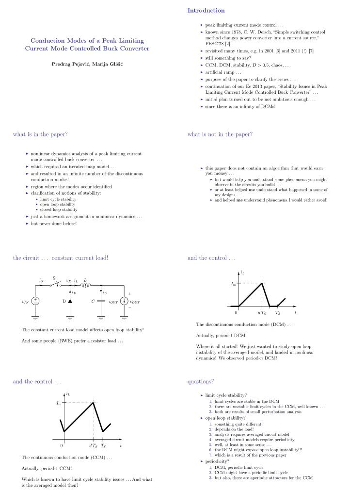
the circuit . . . constant current load! and the control . . . i L S i S v X i L L I m i D i C + + v IN D C i OUT v OUT − − 0 d T S T S t The discontinuous conduction mode (DCM) . . . The constant current load model affects open loop stability! Actually, period-1 DCM! And some people (RWE) prefer a resistor load . . . Where it all started! We just wanted to study open loop instability of the averaged model, and landed in nonlinear dynamics! We observed period- n DCM! and the control . . . questions? i L ◮ limit cycle stability? 1. limit cycles are stable in the DCM I m 2. there are unstable limit cycles in the CCM, well known . . . 3. both are results of small perturbation analysis ◮ open loop stability? 1. something quite different! 2. depends on the load! 3. analysis requires averaged circuit model 4. averaged circuit models require periodicity 5. well, at least in some sense . . . 0 d T S T S t 6. the DCM might expose open loop instability!!! 7. which is a result of the previous paper The continuous conduction mode (CCM) . . . ◮ periodicity? 1. DCM, periodic limit cycle Actually, period-1 CCM! 2. CCM might have a periodic limit cycle 3. but also, there are aperiodic attractors for the CCM Which is known to have limit cycle stability issues . . . And what is the averaged model then?

  2. clarifications needed? clarifications needed? I m = 0 . 5 A I m = 0 . 5 A 0 . 50 0 . 50 0 . 45 0 . 45 0 . 40 0 . 40 0 . 35 0 . 35 i L , i OUT [ A ] 0 . 30 i L , i OUT [ A ] 0 . 30 0 . 25 0 . 25 0 . 20 0 . 20 0 . 15 0 . 15 0 . 10 0 . 10 0 . 05 0 . 05 0 . 00 0 1 2 3 4 5 6 7 8 9 10 11 12 0 . 00 0 1 2 3 4 5 6 7 8 9 10 11 12 v OUT [ V ] v OUT [ V ] But, we obtained this, since in the CCM for D > 1 2 the limit We expected this, since we assumed period-1 stable limit cycle cycle is unstable, and we reach stable period- n stable limit cycle operation . . . in the DCM; nothing to say about open loop stability! steady state waveform of i L , . . . “twin peaks” just a closer look . . . v OUT = 10 . 123190 V ; I m = 0 . 5 A ; I OUT = 0 . 2 A 0 . 5 0 . 4 0 . 5 0 . 3 i L [ A ] 0 . 4 0 . 2 0 . 3 i L [ A ] 0 . 1 0 . 2 0 . 0 10 . 0 10 . 5 11 . 0 11 . 5 12 . 0 0 . 1 v OUT [ V ] 0 . 0 For the thin lines we have a closed-form solution . . . − 0 . 1 0 5 10 15 20 And we know what is going on there . . . twin-peaks (yellow) t [ µ s ] and triangular (red) DCM waveforms . . . infinity of DCMs . . . actually happens . . . Reduction to a Switching Cell Model 1 . 2 S 1 . 0 i S v X i L L 0 . 8 i D 0 . 6 + + v IN D v OUT − − i L [ A ] 0 . 4 0 . 2 0 . 0 − 0 . 2 used to draw i L , to compute i L . . . − 0 . 4 v IN , v OUT assumed constant over T S . . . 0 5 10 15 20 25 30 35 40 45 50 t [ µ s ] circuit equations . . . methods applied . . . L d i L ◮ numerical simulation of iterated maps dt = v L ◮ Python, PyLab, lists . . . ◮ a way to generalize results and conclusions?  V IN − V OUT , S − on , D − off ◮ normalization!  v L = − V OUT , S − off , D − on ◮ I’m becoming boring! 0 , S − off , D − off 

  3. normalization . . . voilà! V base = V IN : v m � V IN d j L M IN = 1 = m L dτ M � V OUT V IN  1 − M, S − on , D − off  I base = V IN / ( f S L ) : m L = − M, S − off , D − on 0 , S − off , D − off  j � f S L i V IN T base = T S : τ � t T S Discrete Time Model of the Switching Cell and when we get it . . . averaged circuit model! S i S v X i L L i C + i L C i OUT v OUT i D − + + v IN D v OUT − − C d v OUT = i L − i OUT d t All we need is j L as a function of J m and M ! Decoupled! iterated map, case 1, no switching iterated map, case 2, switch turn-off j L j L J m J m j L (1) j L (1) j L (0) j L (0) 0 τ 1 1 τ 0 1 τ iterated map, case 3, switch turn-off, diode turn-off iterated map model . . . j L ◮ essentially j L ( n ) as a function of j L ( n − 1) , M , and J m ◮ auxiliary, compute the charge q n carried over each period J m and store it ◮ equations are in the paper . . . j L (0) ◮ simulation? numerical solution? ◮ specify M and J m j L (1) = 0 ◮ start from j L (0) = 0 , at least for the CCM ◮ iterate till j L ( k ) = 0 ; we got the periodicity! ◮ sum all the charges, Q = � n = 1 k q k 0 τ 1 1 τ ◮ j L = j OUT = Q/k ◮ all the rest is the matter of presentation . . . τ 1 + τ 2

  4. A Glimpse on the Period-1 Model Conduction Modes ◮ assumed period-1 operation, regardless the limit cycle ◮ effects caused by the period-1 limit cycle instability for stability supposed-to-be CCM ◮ DCM occurs for J m < M (1 − M ) ◮ where the phenomena occur? ◮ CCM occurs for J m > M (1 − M ) 1. M > 1 2 to ensure the period-1 limit cycle instability J 2 ◮ in DCM j OUT = 2. J m > M (1 − M ) to put period-1 mode in the continuous m 2 M (1 − M ) conduction ◮ in CCM j OUT = J m − 1 2 M (1 − M ) 3. J m < M to allow the inductor discharge over one period; ◮ open loop instability for d j OUT this is new ! > 0 dM ◮ what happens? start from zero, instability, eventually J 2 m (2 M − 1) ◮ in DCM d j OUT = dM 2( M − 1) 2 M 2 return to zero; once returned, “it will start again, it ◮ in CCM d j OUT = M − 1 won’t be any different, will be exactly the same” dM 2 ◮ in both cases open loop instability for M > 1 ◮ . . . and this is period- n DCM! 2 ◮ elementary? chart of modes DCM-1 period- n CCM 1 period-1 CCM J m period- n DCM 1 / 2 1 / 4 period-1 DCM 0 0 1 / 2 1 M DCM-2 DCM-3 DCM-4 DCM-5

  5. DCM-6 DCM-7 DCM-8 DCM-9 DCM-10 dependence of the period number on M and J m j OUT ( M, J m ) , period-1 assumed Output Current and Stability ◮ j OUT = j L ◮ interested in j OUT ( M, J m ) ◮ open loop stability for d j OUT < 0 d M ◮ comparison to period-1 model

  6. j OUT ( M, J m ) , actual j OUT ( M, J m ) j OUT ( M, J m ) in 3D j OUT ( M, J m ) in 3D, period-1 stability, different than 50 : 50 Conclusions 1 ◮ analysis of a PLCMC buck converter ◮ reduction to a switching cell ◮ discrete-time model ◮ normalized discrete time model ◮ limit cycle instability (CCM) causes all the problems . . . ◮ limit cycle instability is different than the open loop instability ◮ the converter might operate in period- n discontinuous conduction mode, stable limit cycle ◮ region where period- n DCM occurs identified ◮ or it can stay in some sort of period- n CCM ◮ for averaged models it is nice to have periodic behavior . . . Conclusions 2 ◮ control model of the switching cell “derived”, j OUT ( M, J m ) ◮ . . . applying simulation of the normalized discrete-time model ◮ open loop stability analyzed ◮ instability of the period-1 limit cycle in CCM modifies the model . . . ◮ resulting in a complex behavior . . . ◮ where small-signal models are of limited value ◮ conclusion: avoid period- n modes ◮ which we knew before ◮ but I understand it better now!

Download Presentation
Download Policy: The content available on the website is offered to you 'AS IS' for your personal information and use only. It cannot be commercialized, licensed, or distributed on other websites without prior consent from the author. To download a presentation, simply click this link. If you encounter any difficulties during the download process, it's possible that the publisher has removed the file from their server.

Recommend


More recommend