Introduction Introduction UNIVERSITY OF TECHNOLOGY, SYDNEY - - PowerPoint PPT Presentation

introduction introduction
SMART_READER_LITE
LIVE PREVIEW

Introduction Introduction UNIVERSITY OF TECHNOLOGY, SYDNEY - - PowerPoint PPT Presentation

Introduction Introduction UNIVERSITY OF TECHNOLOGY, SYDNEY UNIVERSITY OF TECHNOLOGY, SYDNEY FACULTY OF ENGINEERING FACULTY OF ENGINEERING 48550 Electrical Energy Technology 48550 Electrical Energy Technology The reluctance motor is an


slide-1
SLIDE 1

UNIVERSITY OF TECHNOLOGY, SYDNEY UNIVERSITY OF TECHNOLOGY, SYDNEY FACULTY OF ENGINEERING FACULTY OF ENGINEERING

48550 Electrical Energy Technology 48550 Electrical Energy Technology

Switched Reluctance Motors Switched Reluctance Motors

Topics to cover:

  • 1. Introduction
  • 2. Structures & Torque Production
  • 3. Drive Circuits
  • 4. Performance

Introduction Introduction

The reluctance motor is an electric motor in which torque is produced by the tendency

  • f its moveable part to move to a position

where the inductance of the excited winding is maximized.
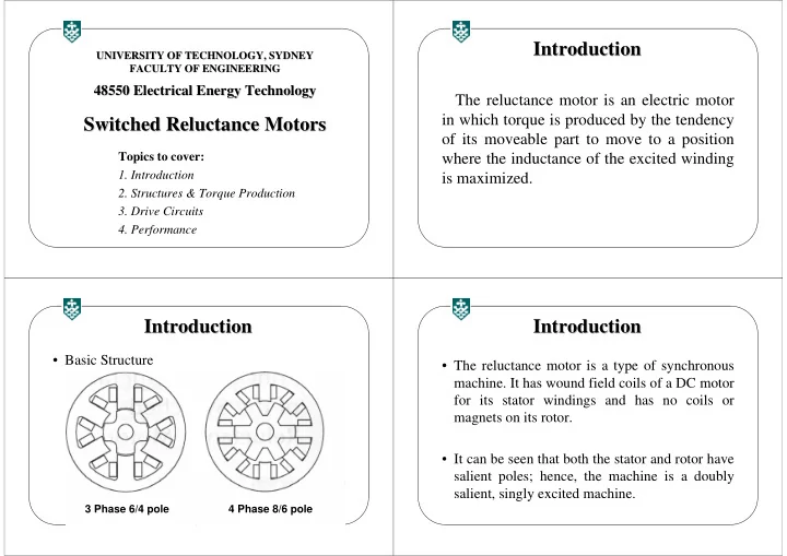
  • Basic Structure

Introduction Introduction

3 Phase 6/4 pole 4 Phase 8/6 pole

  • The reluctance motor is a type of synchronous
  • machine. It has wound field coils of a DC motor

for its stator windings and has no coils or magnets on its rotor.

  • It can be seen that both the stator and rotor have

salient poles; hence, the machine is a doubly salient, singly excited machine.

Introduction Introduction

slide-2
SLIDE 2

Introduction Introduction

The SR motor is designed for efficient power conversion at high speeds comparable with those of the permanent magnet brushless DC motor.

Introduction Introduction

The particular advantages are:

(1) simple rotor structure, possibly with low inertia; (2) simple and reliable stator windings; (3) major loss on the stator, which is easy to cool; (4) higher permissible rotor temperature since there are no magnets; (5) simple unipolar drive; (6) high starting torque without inrush currents; (7) ability to run at extremely high speeds; (8) easy adjustment of the torque/speed characteristic to meet the application requirements.

SRM Configurations SRM Configurations SRM Configurations SRM Configurations -

  • Cont.

Cont. An Axial Field SRM A 8/6 poles short flux path SRM

slide-3
SLIDE 3

SRM Configurations SRM Configurations -

  • Cont.

Cont.

A Single phase SRM A permanent magnet

  • n the stator is used

to pull the rotor away from the alignment,

  • r to an appropriate

position, so as to enable the generation

  • f maximum electro-

magnetic torque.

SRM Configurations SRM Configurations -

  • Cont.

Cont.

A three phase linear SRM

Operation Principles Operation Principles

Cross sectional model of a three phase VR motor, winding arrangement, and equilibrium position with phase 1 excited

How rotor rotates when excitation is switched from Ph1 to Ph2

Operation Principles Operation Principles -

  • Cont.

Cont.

slide-4
SLIDE 4

Rotor rotation as switching sequence proceeds in a three phase VR motor

Operation Principles Operation Principles -

  • Cont.

Cont.

Operation Principles Operation Principles -

  • Cont.

Cont.

Therefore, the conduction angle for the phase current is controlled and synchronized with the rotor position, usually by means of a shaft position sensor. Since the movement of the rotor, and hence the production of torque and power, involves a switching

  • f currents into stator windings when there is a

variation of reluctance, this variable speed SR motor is referred to as a switched reluctance motor (SRM).

Operation Principles Operation Principles -

  • Cont.

Cont.

The torque production in SRM can be explained using the elementary principle of electro- mechanical energy conversion. The incremental mechanical energy in terms of the electromagnetic torque and change in rotor position is:

Torque Production Torque Production

m e

W T θ Δ = Δ

slide-5
SLIDE 5

The electromagnetic torque is then:

where: L(θ, i) is the stator inductance at a particular position, and i the stator phase current.

Torque Production Torque Production -

  • Cont.

Cont.

' ' 2

( , ) 2

f f m e

W W W L i i T θ θ θ θ θ Δ ∂ Δ ∂ = = = = ⋅ Δ Δ ∂ ∂ Torque Production Torque Production -

  • Cont.

Cont.

  • 1. The torque is proportional to the square of the current

and hence, the current can be unipolar to produce unidirectional torque.

  • 2. Since the torque is proportional to the square of the

current, it has a good starting torque.

  • 3. Because the stator inductance is nonlinear, a simple

equivalent circuit development for SRM is not possible.

  • The torque characteristics of SRM are

dependent on the relationship between flux linkages and rotor position as a function of current.

Torque Production Torque Production -

  • Cont.

Cont.

  • 0 ~ θ1 : Te = 0
  • θ1 ~ θ2: Te > 0
  • θ2 ~ θ3: Te = 0
  • θ3 ~ θ4: Te < 0
  • θ4 ~ θ5: Te = 0

Torque Production Torque Production -

  • Cont.

Cont.

slide-6
SLIDE 6
  • For rectangular currents, it can be seen that the

motoring torque is produced for a short duration in pulsed form, resulting in a large torque ripple.

  • Two ways can be applied to reduce the torque

ripples:

–Optimal design of inductance profile –Shape the phase current

Torque Production Torque Production -

  • Cont.

Cont.

Electrical equation

Equivalent Circuit Equivalent Circuit

( , ) ( , ) ( , )

s m s

di dL i V R i L i i dt d di R i L i e dt θ θ ω θ θ = + + = + +

Equivalent Circuit Equivalent Circuit -

  • Cont.

Cont.

SRM Drive System SRM Drive System

Switched Reluctance Motor = Variable Reluctance Motor + Electronic Commutator

Logic Circuit DC Supply Reluctance Motor Position Sensor Electronic Commutator Variable

slide-7
SLIDE 7

Position Sensors Position Sensors

Commonly used position sensors are:

Phototransistors and photodiodes – Hall elements – Magnetic sensors – Pulse encoders – Variable Differential Transformers

Position Sensors Position Sensors -

  • Cont.

Cont.

Phototransistor position sensor Hall element position sensor

Position Sensors Position Sensors -

  • Cont.

Cont.

  • Since the torque in SRM drives is

independent of the excitation current polarity, the SRM drives require only one power switch per phase winding.

Power Converters for SRM Power Converters for SRM

slide-8
SLIDE 8

Asymmetric Bridge Converter Asymmetric Bridge Converter Asymmetric Bridge Converter Asymmetric Bridge Converter -

  • Cont.

Cont.

Operation waveforms

( (n+1) switches topology n+1) switches topology -

  • Cont.

Cont.

Bifilar Type Drive Circuit Bifilar Type Drive Circuit

slide-9
SLIDE 9

Bifilar Type Drive Circuit Bifilar Type Drive Circuit -

  • Cont.

Cont.

  • The voltage across the

power switch can be very much higher than the source voltage.

  • The bifilar winding

increases the complexity

  • f the motor.

C C-

  • Dump Converter

Dump Converter C C-

  • Dump Converter

Dump Converter -

  • Cont.

Cont.

C-Dump converter has the advantage

  • f minimum power

switches allowing independent phase current control. The torque produced in one phase for motoring and regeneration

Control of SRM Control of SRM.

.

slide-10
SLIDE 10

Control of SRM Control of SRM -

  • Cont..

Cont..

An average torque will result due to the combined instantaneous values of torque pulses of all machine phases. The average torque is controlled by adjusting the magnitude of winding current Ip

  • r by varying the

dwell angle θd.

Control of SRM Control of SRM -

  • Cont..

Cont..

Control of SRM Control of SRM -

  • Cont..

Cont..

Typical phase current waveforms at different speeds and advance angles.

Torque/Speed Characteristic Torque/Speed Characteristic

General torque/speed characteristic of SR motor