Introduction cont. Lecture goal: Overview: get context, overview, - - PDF document

introduction cont
SMART_READER_LITE
LIVE PREVIEW

Introduction cont. Lecture goal: Overview: get context, overview, - - PDF document

Introduction cont. Lecture goal: Overview: get context, overview, access net, physical media feel of networking performance: loss, delay more depth, detail later in course protocol layers, service models approach:


slide-1
SLIDE 1

1

9/9-02 Datorkommunikation & Internet, Anders broberg, Umu - Introduction 1

Introduction cont.

Lecture goal:

¸ get context, overview,

“feel” of networking

¸ more depth, detail later

in course

¸ approach:

  • descriptive
  • use Internet as

example

Overview:

¸ access net, physical media ¸ performance: loss, delay ¸ protocol layers, service models ¸ backbones, NAPs, ISPs

9/9-02 Datorkommunikation & Internet, Anders broberg, Umu - Introduction 2

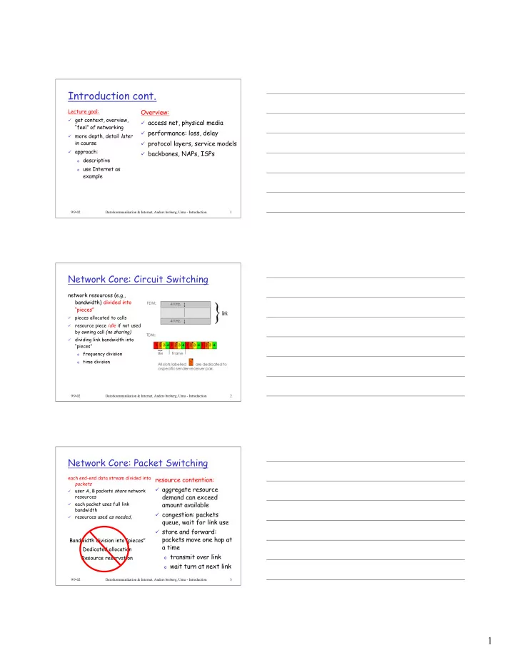
Network Core: Circuit Switching

network resources (e.g., bandwidth) divided into “pieces”

¸

pieces allocated to calls

¸

resource piece idle if not used by owning call (no sharing)

¸

dividing link bandwidth into “pieces”

  • frequency division
  • time division

9/9-02 Datorkommunikation & Internet, Anders broberg, Umu - Introduction 3

Network Core: Packet Switching

each end-end data stream divided into packets

¸

user A, B packets share network resources

¸

each packet uses full link bandwidth

¸

resources used as needed,

resource contention:

¸ aggregate resource

demand can exceed amount available

¸ congestion: packets

queue, wait for link use

¸ store and forward:

packets move one hop at a time

  • transmit over link
  • wait turn at next link

Bandwidth division into “pieces” Dedicated allocation Resource reservation

slide-2
SLIDE 2

2

9/9-02 Datorkommunikation & Internet, Anders broberg, Umu - Introduction 4

Network Core: Packet Switching

Packet-switching versus circuit switching: human restaurant analogy

A B C

10 Mbs Ethernet 1.5 Mbs 45 Mbs

D E

statistical multiplexing

queue of packets waiting for output link

9/9-02 Datorkommunikation & Internet, Anders broberg, Umu - Introduction 5

Network Core: Packet Switching

Packet-switching: store and forward behavior Example

¸ 7.5 Mbit message ¸ 1.5 Mbps link transmission

rate

¸ 5000 1.5 Kbit packets

9/9-02 Datorkommunikation & Internet, Anders broberg, Umu - Introduction 6

Packet switching versus circuit switching

¸

1 Mbit link

¸

each user:

  • 100Kbps when “active”
  • active 10% of time

¸

circuit-switching:

  • 10 users

¸

packet switching:

  • with 35 users, probability > 10

active less that .004

Packet switching allows more users to use network! N users 1 Mbps link

slide-3
SLIDE 3

3

9/9-02 Datorkommunikation & Internet, Anders broberg, Umu - Introduction 7

Packet switching versus circuit switching

¸ Great for bursty data

  • resource sharing
  • no call setup

¸ Excessive congestion: packet delay and loss

  • protocols needed for reliable data transfer,

congestion control

¸ Q: How to provide circuit-like behavior?

  • bandwidth guarantees needed for audio/video

apps still an unsolved problem (chapter 6) Is packet switching a “slam dunk winner?”

9/9-02 Datorkommunikation & Internet, Anders broberg, Umu - Introduction 8

Packet-switched networks: routing

¸

Goal: move packets among routers from source to destination

  • we’ll study several path selection algorithms (chapter 4)

¸

datagram network:

  • destination address determines next hop
  • routes may change during session
  • analogy: driving, asking directions

¸

virtual circuit network:

  • each packet carries tag (virtual circuit ID), tag determines next hop
  • fixed path determined at call setup time, remains fixed thru call
  • routers maintain per-call state

9/9-02 Datorkommunikation & Internet, Anders broberg, Umu - Introduction 9

Access networks and physical media

Q: How to connection end systems to edge router?

¸ residential access nets ¸ institutional access networks

(school, company)

¸ mobile access networks

Keep in mind:

¸ bandwidth (bits per second)

  • f access network?

¸ shared or dedicated?

slide-4
SLIDE 4

4

9/9-02 Datorkommunikation & Internet, Anders broberg, Umu - Introduction 10

Residential access: point to point access

¸ Dialup via modem

  • up to 56Kbps direct access to

router (conceptually)

¸ ISDN: intergrated services

digital network: 128Kbps all- digital connect to router

¸ ADSL: asymmetric digital

subscriber line

  • up to 1 Mbps home-to-router
  • up to 8 Mbps router-to-home
  • Ordinary PSTN

9/9-02 Datorkommunikation & Internet, Anders broberg, Umu - Introduction 11

Residential access: cable modems

¸ HFC: hybrid fiber coax

  • asymmetric: up to 10Mbps

upstream, 1 Mbps downstream ¸ network of cable and

fiber attaches homes to ISP router

  • shared access to router

among home

  • issues: congestion,

dimensioning

9/9-02 Datorkommunikation & Internet, Anders broberg, Umu - Introduction 12

Institutional access: local area networks

¸ company/univ local area

network (LAN) connects end system to edge router

¸ Ethernet:

  • shared or dedicated

cable connects end system and router

  • 10 Mbs, 100Mbps,

Gigabit Ethernet

¸ LANs: chapter 5

slide-5
SLIDE 5

5

9/9-02 Datorkommunikation & Internet, Anders broberg, Umu - Introduction 13

Wireless access networks

¸ shared wireless access

network connects end system to router

¸ wireless LANs:

  • radio spectrum replaces

wire

  • e.g., Lucent Wavelan 10

Mbps ¸ wider-area wireless

access

  • GPRS (General Packet

Radio Service)

base station mobile hosts router

9/9-02 Datorkommunikation & Internet, Anders broberg, Umu - Introduction 14

Physical Media

¸ physical link:

transmitted data bit propagates across link

¸ guided media:

  • signals propagate in

solid media: copper, fiber ¸ unguided media:

  • signals propagate freely

e.g., radio

Twisted Pair (TP)

¸ two insulated copper

wires

  • Category 3: traditional

phone wires, 10 Mbps ethernet

  • Category 5 TP:

100Mbps ethernet

9/9-02 Datorkommunikation & Internet, Anders broberg, Umu - Introduction 15

Physical Media: coax, fiber

Coaxial cable:

¸ wire (signal carrier)

within a wire (shield)

  • baseband: single channel
  • n cable
  • broadband: multiple

channel on cable ¸ bidirectional ¸ common use in 10Mbps

Ethernet

Fiber optic cable:

¸ glass fiber carrying light

pulses

¸ high-speed operation:

  • 100Mbps Ethernet
  • high-speed point-to-point

transmission (e.g., 5 Gbps) ¸ low error rate

slide-6
SLIDE 6

6

9/9-02 Datorkommunikation & Internet, Anders broberg, Umu - Introduction 16

Physical media: radio

¸ signal carried in

electromagnetic spectrum

¸ no physical “wire” ¸ bidirectional ¸ propagation

environment effects:

  • reflection
  • obstruction by objects
  • interference

Radio link types:

¸ microwave

  • e.g. up to 45 Mbps channels

¸ LAN (e.g., waveLAN)

  • 2Mbps, 11Mbps

¸ wide-area (e.g., cellular)

  • e.g. GPRS, 10’s Kbps

¸ satellite

  • up to 50Mbps channel (or

multiple smaller channels)

  • 270 msec end-end delay

9/9-02 Datorkommunikation & Internet, Anders broberg, Umu - Introduction 17

Delay in packet-switched networks

packets experience delay

  • n end-to-end path

¸ four sources of delay

at each hop

¸ nodal processing:

  • check bit errors
  • determine output link

¸ queuing

  • time waiting at output link

for transmission

  • depends on congestion

level of router

A B

propagation transmission nodal processing queuing

9/9-02 Datorkommunikation & Internet, Anders broberg, Umu - Introduction 18

Delay in packet-switched networks

Transmission delay:

¸ R=link bandwidth (bps) ¸ L=packet length (bits) ¸ time to send bits into

link = L/R Propagation delay:

¸ d = length of physical link ¸ s = propagation speed in

medium (~2x10⁸ m/sec)

¸ propagation delay = d/s

A B

propagation transmission nodal processing queueing

Note: s and R are very different quantities!

slide-7
SLIDE 7

7

9/9-02 Datorkommunikation & Internet, Anders broberg, Umu - Introduction 19

Queuing delay (revisited)

¸ R=link bandwidth (bps) ¸ L=packet length (bits) ¸ a=average packet arrival

rate

traffic intensity = La/R

¸ La/R ~ 0: average queuing delay small ¸ La/R -> 1: delays become large ¸ La/R > 1: more “work” arriving than can be

serviced, average delay infinite!

9/9-02 Datorkommunikation & Internet, Anders broberg, Umu - Introduction 20

Protocol “Layers”

Networks are complex!

¸ many “pieces”:

  • hosts
  • routers
  • links of various

media

  • applications
  • protocols
  • hardware,

software Question:

Is there any hope of organizing structure of network? Or at least our discussion of networks?

9/9-02 Datorkommunikation & Internet, Anders broberg, Umu - Introduction 21

Organization of air travel

¸ a series of steps

ticket (purchase) baggage (check) gates (load) runway takeoff airplane routing ticket (complain) baggage (claim) gates (unload) runway landing airplane routing airplane routing

slide-8
SLIDE 8

8

9/9-02 Datorkommunikation & Internet, Anders broberg, Umu - Introduction 22

Organization of air travel: a different view

Layers: each layer implements a service

  • via its own internal-layer actions
  • relying on services provided by layer below

ticket (purchase) baggage (check) gates (load) runway takeoff airplane routing ticket (complain) baggage (claim) gates (unload) runway landing airplane routing airplane routing

9/9-02 Datorkommunikation & Internet, Anders broberg, Umu - Introduction 23

Layered air travel: services

Counter-to-counter delivery of person+bags baggage-claim-to-baggage-claim delivery people transfer: loading gate to arrival gate runway-to-runway delivery of plane airplane routing from source to destination

9/9-02 Datorkommunikation & Internet, Anders broberg, Umu - Introduction 24

Distributed implementation of layer functionality

ticket (purchase) baggage (check) gates (load) runway takeoff airplane routing ticket (complain) baggage (claim) gates (unload) runway landing airplane routing

airplane routing

Departing airport arriving airport

intermediate air traffic sites

airplane routing airplane routing

slide-9
SLIDE 9

9

9/9-02 Datorkommunikation & Internet, Anders broberg, Umu - Introduction 25

Why layering?

Dealing with complex systems:

¸ explicit structure allows identification, relationship of

complex system’s pieces

  • layered reference model for discussion

¸ modularization eases maintenance, updating of system

  • change of implementation of layer’s service transparent

to rest of system

  • e.g., change in gate procedure doesn’t affect rest of

system

¸ layering considered harmful?

9/9-02 Datorkommunikation & Internet, Anders broberg, Umu - Introduction 26

Internet protocol stack

¸ application: supporting network applications

  • ftp, smtp, http

¸ transport: host-host data transfer

  • tcp, udp

¸ network: routing of datagrams from source

to destination

  • ip, routing protocols

¸ link: data transfer between neighboring

network elements

  • ppp, ethernet

¸ physical: bits “on the wire”

application transport network link physical

9/9-02 Datorkommunikation & Internet, Anders broberg, Umu - Introduction 27

Layering: logical communication

application transport network link physical application transport network link physical application transport network link physical application transport network link physical network link physical

Each layer:

¸ distributed ¸ “entities”

implement layer functions at each node

¸ entities perform

actions, exchange messages with peers

slide-10
SLIDE 10

10

9/9-02 Datorkommunikation & Internet, Anders broberg, Umu - Introduction 28

Layering: logical communication

application transport network link physical application transport network link physical application transport network link physical application transport network link physical network link physical data data

E.g.: transport

¸ take data from app ¸ add addressing,

reliability check info to form “datagram”

¸ send datagram to

peer

¸ wait for peer to

ack receipt

¸ analogy: post

  • ffice

data

transport transport

ack

9/9-02 Datorkommunikation & Internet, Anders broberg, Umu - Introduction 29

Layering: physical communication

application transport network link physical application transport network link physical application transport network link physical application transport network link physical network link physical data data

9/9-02 Datorkommunikation & Internet, Anders broberg, Umu - Introduction 30

Protocol layering and data

Each layer takes data from above

¸ adds header information to create new data unit ¸ passes new data unit to layer below

application transport network link physical application transport network link physical source destination

M M M M Ht Ht Hn Ht Hn Hl M M M M Ht Ht Hn Ht Hn Hl message segment datagram frame

slide-11
SLIDE 11

11

9/9-02 Datorkommunikation & Internet, Anders broberg, Umu - Introduction 31

ISO/OSI protocol stack

¸

ISO: International Standards Organisation

¸

OSI: Open System Interconnection

Application Presentation Session Transport End host One or more nodes within the network Network Data link Physical Network Data link Physical Network Data link Physical Application Presentation Session Transport End host Network Data link Physical

9/9-02 Datorkommunikation & Internet, Anders broberg, Umu - Introduction 32

Internet structure: network of networks

¸ roughly hierarchical ¸ national/international backbone

providers (NBPs)

  • e.g. BBN/GTE, Sprint, AT&T,

IBM, UUNet

  • interconnect (peer) with each
  • ther privately, or at public

Network Access Point (NAPs) ¸ regional ISPs

  • connect into NBPs

¸ local ISP, company

  • connect into regional ISPs

NBP A NBP B NAP NAP

regional ISP regional ISP local ISP local ISP

9/9-02 Datorkommunikation & Internet, Anders broberg, Umu - Introduction 33

SUNET

slide-12
SLIDE 12

12

9/9-02 Datorkommunikation & Internet, Anders broberg, Umu - Introduction 34

NORDUnet

9/9-02 Datorkommunikation & Internet, Anders broberg, Umu - Introduction 35

Summary

Covered a “ton” of material!

¸ Internet overview ¸ what’s a protocol? ¸ network edge, core,

access network

¸ performance: loss, delay ¸ layering and service

models

¸ backbones, NAPs, ISPs

You now hopefully have:

¸ context, overview,

“feel” of networking

¸ more depth, detail

later in course