
1
Interaction Model
Distributed algorithm vs. simple algorithm Difficulties
Complex Hard to predict: executing rate, transmission rate No general state
Performance of communication channels
Latency; Bandwidth; Jitter
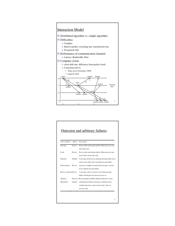
Computer clocks
clock drift rate: difference from perfect clock Correction [ch11]
- Time server [Cristian, 1989]
- Logical clock
send receive send receive m1 m
2
2 1 3 4 X Y Z Physical time A m3 receive receive send receive receive receive t1 t2 t3 receive receive m2 m
1
2
Omission and arbitrary failures
Class of failure Affects Description Fail-stop Process Process halts and remains halted. Other processes may detect this state. Crash Process Process halts and remains halted. Other processes may not be able to detect this state. Omission Channel A message inserted in an outgoing message buffer never arrives at the other end’s incoming message buffer. Send-omission Process A process completes a send,but the message is not put in its outgoing message buffer. Receive-omissionProcess A message is put in a process’s incoming message buffer, but that process does not receive it. Arbitrary (Byzantine) Process or channel Process/channel exhibits arbitrary behaviour: it may send/transmit arbitrary messages at arbitrary times, commit omissions; a process may stop or take an incorrect step.