
SLIDE 1
Australian Centre for Space Engineering Research (ACSER)
Improve Vehicle Positioning in Cooperative Intelligent Transport - - PowerPoint PPT Presentation
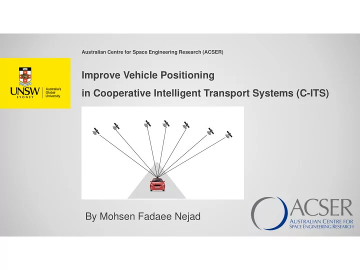
Australian Centre for Space Engineering Research (ACSER) Improve Vehicle Positioning in Cooperative Intelligent Transport Systems (C-ITS) By Mohsen Fadaee Nejad Cooperative Intelligent Transport Systems (C-ITS) A revolution in transport
Australian Centre for Space Engineering Research (ACSER)
Australia's largest C-ITS project (TfNSW): This trial has fitted C-ITS technology to:
1
2
(sub-metre) and where-in-lane-level (decimetre).
cannot be reliably achieved with standalone GNSS and low cost receivers.
where-in-lane-level applications it is 0.1 second (10 Hz).
interoperability, are also critical. Bullet point text 3
4
5
6
7
8
9
10
11
GNSS measurements retrieved from Android devices
pseudorange.
pseudorange.
data file.
derived data file.
12
GLONASS, Galileo, BeiDou and QZSS) and multi-frequency
L1, L5, E1 and E5 signals tracked by a dual-frequency chip
manipulating the plots.
reports of receivers, evaluating the API implementation, received signal, clock behavior, and measurement accuracy.
13
14
Tool provides interactive plots
15
The RF column shows the following data:
strongest signals.
(C/No).
16
The clock column shows the following data:
PVT.
the duty cycle of the primary oscillator.
17
The measurements column shows the following data:
raw pseudoranges. The weighting is done using the reported uncertainty of each measurement, which is part of the raw measurement API spec.
18
received signal, clock behavior, and measurement accuracy.
the receiver passed or failed the test based on the performance measured against known benchmarks.
manufacturers, who can use it as they iterate through the design and implementation of new devices.
19
The Compare tab provides a side-by-side comparison, of C/No from several GNSS log files, which is useful when comparing the RF performance of several devices.
20