ICF Overview and Z Joel Lash, Ph. D. Senior Manager, Z Facility - - PowerPoint PPT Presentation

icf overview and z
SMART_READER_LITE
LIVE PREVIEW

ICF Overview and Z Joel Lash, Ph. D. Senior Manager, Z Facility - - PowerPoint PPT Presentation

ICF Overview and Z Joel Lash, Ph. D. Senior Manager, Z Facility R&D Sandia National Laboratories, Albuquerque, NM, USA Laser Magnetization Compression Heating Sandia National Laboratories is a multi-program laboratory managed and


slide-1
SLIDE 1

Sandia National Laboratories is a multi-program laboratory managed and operated by Sandia Corporation, a wholly owned subsidiary of Lockheed Martin Corporation, for the U.S. Department of Energy’s National Nuclear Security Administration under contract DE-AC04-94AL85000.

Magnetization Laser Heating Compression

ICF Overview and Z

Joel Lash, Ph. D.

Senior Manager, Z Facility R&D Sandia National Laboratories, Albuquerque, NM, USA

slide-2
SLIDE 2

Achieving significant fusion yields has so far required taking extreme measures…

2

National Ignition Facility: World’s largest and most powerful laser

slide-3
SLIDE 3

The U.S. Inertial Confinement Fusion (ICF) Program is pursuing three main approaches to fusion ignition

3

slide-4
SLIDE 4

X-ray driven implosions on the National Ignition Facility remain the primary approach, but the failure to achieve ignition has encouraged broader thinking in the USA

  • Highest yields on the facility to date

have been < 1x10¹⁶ neutrons (35- 100x below ignition)

  • The highest yield shots do show

alpha heating

  • The NNSA Lab directors sent a letter

last year to Gen. Frank Klotz endorsing the need for “multi-MJ fusion yields”

  • Significant uncertainty remains as to

whether ignition on NIF is possible, sets the stage for four choices:

  • A bigger laser for x-ray drive
  • Convert NIF to direct drive
  • Pursue a pulsed power driver
  • None of the above

4

Are 3D instabilities limiting the compression?

slide-5
SLIDE 5

Russian Facility (Baikal)

  • 50 MA
  • 150 ns
  • 100 MJ (4 x Z)
  • Stated goal: 25 MJ fusion yield
  • Originally scheduled for completion in

2019, delayed due to oil price collapse

  • If it works, they could have this capability

before the United States

Operating Chinese Facility (PTS)

  • 8 MA
  • 100 ns
  • 8 MJ (1/3 x Z)
  • Successfully duplicating previous

published work worldwide

  • They are even building a 1 ns, 1 kJ

laser facility like Z-Beamlet!

  • They are currently evaluating LTD and

Marx-based architectures

The “None of the above” option has risk. The rest of the world may not be content to follow the United States.

5

Chinese laser scientist to NIF director: “It is no longer acceptable to just follow the United States, we are considering building a bigger laser to achieve ignition.”

slide-6
SLIDE 6

Some context to understand how extreme traditional ICF really is…

6

  • 35:1 convergence ratio
  • Basketball to pea
  • Need <1-2% deviation from

a perfect sphere

  • If an ICF capsule scaled to

the size of earth, it would have to be smoother than earth!

  • 380 km/s implosion
  • NY to LA = 3936 km
  • Would take about 10 s!
  • Faster than a speeding

bullet! (~3000 km/h)

  • 400 Gbar pressure
  • Diamond Anvil Cell

reaches ~6 Mbar

  • Center of sun is

about 250 Gbar!

  • Burn time ~0.2 ns
  • Speed of light: 3x10⁸ m/s
  • Moves 6 cm in 0.2 ns

Anything that we can do to make this less extreme is worth investigating!

slide-7
SLIDE 7

The Sandia Z pulsed power facility uses magnetic pressure to efficiently couple MJs of energy to “targets” at its center

22 MJ peak stored energy 26 MA peak current 100–300 ns pulse lengths

10,000 ft2

Up to 50 Megagauss field Up to100 Mbar drive pressure 15% coupling to load Multi-kJ, 2-TW Z-Beamlet Laser (ZBL) beam path

slide-8
SLIDE 8

Magnetic direct drive is based on efficient use of large currents to create high pressures

33 m 20TW 67 TW 77 TW

MBar

R drive current I Magnetically Driven Implosion 100 MBar at 26 MA and 1 mm Z today couples ~0.5 MJ out

  • f 20 MJ stored to

magnetized liner inertial fusion (MagLIF) target (0.1 MJ in DD fuel).

slide-9
SLIDE 9

The “new” idea: Magneto-inertial fusion is based on the idea that energy and particle transport can be reduced by strong magnetic fields, even in collisional plasmas

9

Heat/energy flow Hot Cold Collisional no B Strong B (perpendicula r to this slide) No collisions Strong B with collisions “Anomalous” heat transport can reduce the benefit of magnetic fields (e.g., in tokamaks) but there remains a significant benefit Heat flow reduced!

slide-10
SLIDE 10

Magnetized Liner Inertial Fusion (MagLIF) is well suited to pulsed power drivers and may reduce fusion requirements

  • Axial magnetization of fuel/liner (Bz0 = 10-30 T)
  • Inhibits thermal conduction losses and traps alphas

(β: 5~80; ωτ>200 at stagnation)

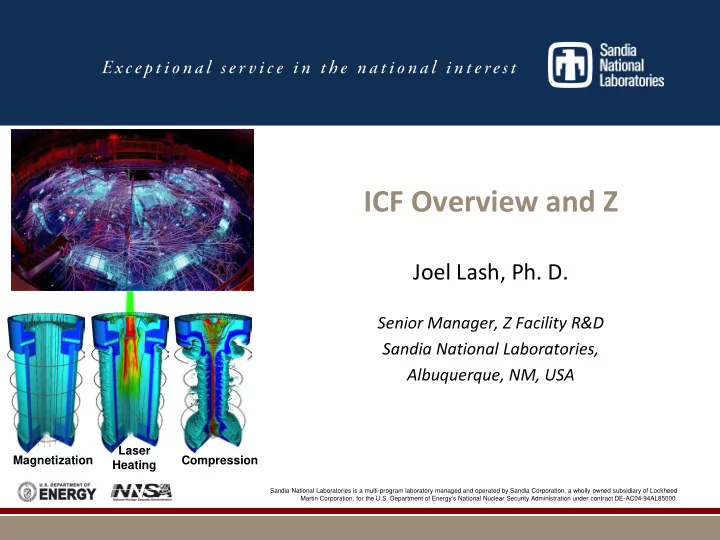
  • Laser heating of fuel (2 kJ initially, 6 kJ planned)
  • Reduces radial fuel compression needed to reach fusion

temperatures (R0/Rf about 25, T0=150-200 eV)

  • Liner compression of fuel (70-100 km/s, ~100 ns)
  • Low velocity allows use of thick liners (R/∆R~6) that are

robust to instabilities and have sufficient ρR at stagnation for inertial confinement

  • This combination allows fusion at ~100x lower fuel

pressure than traditional ICF (~5 Gbar vs. 500 Gbar)

  • 2-D Simulations suggest 100 kJ DT yield may be

possible on Z in future

  • Requires upgrades from our present system

e.g., 10 T  30 T; 2 kJ  4 kJ; 19 MA  24 MA

7.5-10 mm 4-6 mm D2 Fill (~1 mg/cc) Be Liner (AR~6) Laser Preheat 2-4 kJ, 2-4 ns 527 nm

slide-11
SLIDE 11

MagLIF has conservative fuel compression characteristics, but relies on largely untested magneto-inertial fusion principles

  • Low Velocity Implosion
  • Low IFAR
  • Low convergence ratio / volume

compression / fuel ρR

11

Metric X-ray Drive

  • n NIF

100 kJ MagLIF

  • n Z

Pressure

~140-160 Mbar 26 MA at 1 mm is 100 Mbar

Force vs. Radius

Goes as R^2 Goes as 1/R

Peak velocity 350-380 km/s

70-100 km/s

Peak IFAR

13-15 (high foot) to 17-20 8.5

Hot spot CR

35 (high foot) to 45 25

Volume Change

43000x (high) to 91000x 625x

Fuel rho-R

>0.3 g/cm^2 ~0.003 g/cm^2

Liner rho-R

n/a >0.3 g/cm^2

BR

n/a >0.5 MG-cm

Burn time

0.15 to 0.2 ns 1 to 2 ns

T_ion

>4 keV >4 keV

1-D picture*

slide-12
SLIDE 12

Z couples several MJ of energy to the load hardware, ~equivalent to a stick of dynamite, making diagnostic measurements and laser coupling challenging

12

Damage to FOA debris shielding Pre-shot photo of MagLIF load hardware Post-shot photo

slide-13
SLIDE 13

13

X-ray Radiography Imaging Spectra Neutron spectra Nuclear Activation DD DT X-ray Power

MagLIF Z pinch

We use a combination of current, x-ray, and neutron diagnostics to assess the performance of MagLIF implosions.

Load Current

slide-14
SLIDE 14
  • Field Coils:

Helmholtz-like coil pair produce a 10 T uniform axial field w/ ~3 ms rise time

  • ZBL: 1-4 kJ green

laser, 1-4 ns square pulse w/ adjustable prepulse.

  • Power Feed:

Raised feed with a total inductance of 7.3 nH to allow diagnostic access and uniform B-field Field Coils Be Liner/Target Power Feed Coil Support Structure Z-Beamlet Laser (ZBL) A K

z x y

Fuel Fill Line Load-Current B- dots

Present ‘Baseline’ MagLIF Target

50 mm

slide-15
SLIDE 15
  • Be Liner: OD = 5.58 mm, ID

= 4.65 mm, h = 10 mm

  • LEH Window: 1.5 µm thick

Polyimide window.

  • Gas Fill: D2 at 60 PSI

(0.7 mg/cc)

  • Washer: Be washer

supporting LEH window

  • Cushion: Be structure used

to mitigate the wall instability.

  • Return Can: Slotted for

diagnostic access Z-Beamlet Laser LEH Window Be Liner Cushion Washer A K

Present ‘Baseline’ MagLIF Target

10 mm

slide-16
SLIDE 16

We will invest in tritium capability on Z to enable nuclear diagnostics with a few% T by 2020 and 50-50 DT later.

2015 2016 2017 2018 2019 2020

Contained D2, 3He 0.1% T

  • 1% T

3% T 3% T Uncontained D2, 3He D2, 3He 0.1% T 0.3% T 1% T 3% T

Trace T for thermonuclear, Tion studies DD and DT nTOF, yield ratio Advanced nuclear diagnostics GCD, neutron imaging, MRS

  • 0.1% T was shot on Z in 2016 using an

containment system.

  • Uncontained trace T is desired for ICF.
  • Tritium behavior in the Z environment will

be studied as we increase quantities.

  • Moderate investment will likely be

needed for >few% T.

slide-17
SLIDE 17

We are exploring a new pulsed power architecture that may scale better to ignition and high-yield

Cavity Capacitor Capacitor Switch

slide-18
SLIDE 18

Linear Transformer Driver architecture is 2x as efficient as today’s systems and may offer a compelling path forward to reach 0.5-1 GJ yields and meet future Science Program needs

“Z800”

  • 800 TW
  • 52 Meter diameter
  • 61 MA
  • 130 MJ Stored Energy

Fusion Yield 0.5-1 GJ? Burning plasmas

“Z300”

  • 300 TW
  • 35 Meter diameter
  • 47 MA
  • 47 MJ Stored Energy

Yield = Etarget? (About 3-4 MJ) a-dominated plasmas

Z

  • 80 TW
  • 33 Meter diameter
  • 26 MA
  • 22 MJ Stored Energy

Yield = Efuel? (~100kJDT eq) Physics Basis for Z300

Note that 1 GJ ~ 0.25 tons TNT and there will be significant radiation and activation issues, so Z800 is “bold”!

slide-19
SLIDE 19

The entire laboratory will be needed to successfully develop and execute a Z-Next project

Lab-Wide S & T Engagement

Multi-disciplinary science & technology advances New simulation codes and high power computing Materials and Materials Science Nuclear, Mechanical, Electrical Engineering HED target science & technology Pulsed power driver science & technology Project Management and Systems Engineering Tritium handling Nuclear facility design for large fusion yields Systems design for handling of activated hardware Siting challenges Robotics Licensing, regulations, waste handling, and mitigation

Many unique problems need to be solved SMEs and teams from around Sandia (and the complex) will be needed to develop the tools, techniques, and capabilities to succeed on a Z-Next project!

slide-20
SLIDE 20

Questions?