
10/31/2012 1
Graph IRs
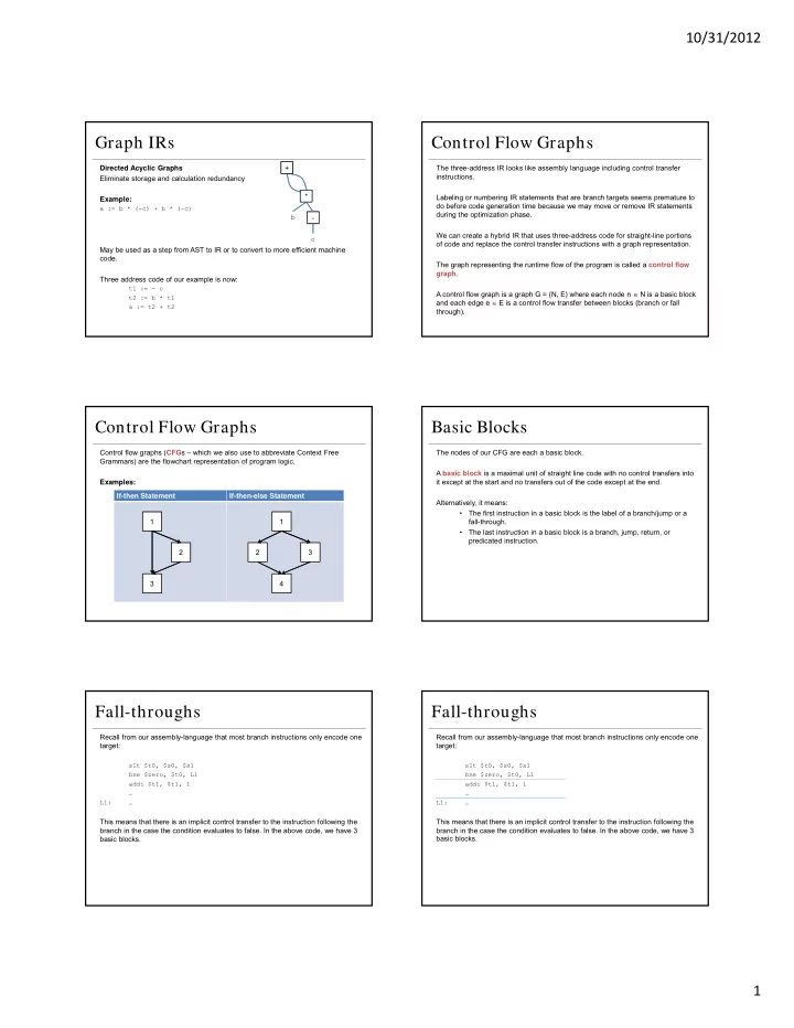
Directed Acyclic Graphs Eliminate storage and calculation redundancy Example:
a := b * (-c) + b * (-c)
May be used as a step from AST to IR or to convert to more efficient machine code. Three address code of our example is now:
t1 := - c t2 := b * t1 a := t2 + t2
- b
c * +
Control Flow Graphs
The three-address IR looks like assembly language including control transfer instructions. Labeling or numbering IR statements that are branch targets seems premature to do before code generation time because we may move or remove IR statements during the optimization phase. We can create a hybrid IR that uses three-address code for straight-line portions
- f code and replace the control transfer instructions with a graph representation.
The graph representing the runtime flow of the program is called a control flow graph. A control flow graph is a graph G = (N, E) where each node n N is a basic block and each edge e E is a control flow transfer between blocks (branch or fall through).
Control Flow Graphs
Control flow graphs (CFGs – which we also use to abbreviate Context Free Grammars) are the flowchart representation of program logic. Examples: If-then Statement If-then-else Statement 1 3 2 1 4 3 2
Basic Blocks
The nodes of our CFG are each a basic block. A basic block is a maximal unit of straight line code with no control transfers into it except at the start and no transfers out of the code except at the end. Alternatively, it means:
- The first instruction in a basic block is the label of a branch/jump or a
fall-through.
- The last instruction in a basic block is a branch, jump, return, or
predicated instruction.
Fall-throughs
Recall from our assembly-language that most branch instructions only encode one target:
slt $t0, $s0, $s1 bne $zero, $t0, L1 addi $t1, $t1, 1 … L1: …
This means that there is an implicit control transfer to the instruction following the branch in the case the condition evaluates to false. In the above code, we have 3 basic blocks.