SLIDE 1 GERDA cryostat safety training
Bernhard Schwingenheuer, MPI Heidelberg
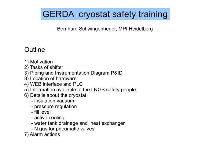
Outline
1) Motivation 2) Tasks of shifter 3) Piping and Instrumentation Diagram P&ID 3) Location of hardware 4) WEB interface and PLC 5) Information available to the LNGS safety people 6) Details about the cryostat
- insulation vacuum
- pressure regulation
- fill level
- active cooling
- water tank drainage and heat exchanger
- N gas for pneumatic valves
7) Alarm actions
SLIDE 2
Why do we need a shift person? 0) operating a 65 m3 cryostat in a 600 m3 water tank is potenially a risky business 1) “everything” is automatized, but there might be situations when a person has to diagnose a problem from above/under-ground and/or to fix s.th. 2) agreement with LNGS: every day shift for cryostat, a GERDA person is underground within 30 min after she/he is called (or a problem reported by GERDA itself), shift list is provided to LNGS Note: after 4 months of operation, no call so far and no problem occurred which required a person to come immediately 3) 365 day of operation has to be shared by more than a few people (especially on weekends) even if the chance to have a problem is low
SLIDE 3 Task of the shifter
0) get acquainted with the system (these slides are on the WEB, HELP on WEB page) and the current status (ELOG) 1) be reachable by phone during the shift (shifter mobile telephone available soon), notification by a) GERDA alarm control via SMS b) LNGS guards Note: GERDA alarm should come first 2) be close to a computer with a WEB browser during your shift 3) need a car to go underground (check access authorization!) 4) try to diagnose a problem
- from outside with the WEB interface (e.g. from your office or home/hotel)
- call an expert in case of questions (phone numbers are stored in the shifter mobile or on WEB),
these are currently Marco Balata, Stefano Gazzana, Luca Ioannucci, Matthias Junker, Karl Tasso Knöpfle, Bernhard Schwingenheuer
- find out whether it is safe to enter underground
- go underground for further diagnostics and actions (if useful and safe)
4) some actions can be done with the WEB interface (e.g. setpoint adjustment for valves),
- thers require to be present underground (e.g. manual operation of valves, after power cut)
5) record any action in the electronic logbook ELOG 6) make an entry into the ELOG server for shifts when you want to take over a shift: http://teran.lngs.infn.it:20000/GERDA_Safety/ Userid and password are the same as for the internal GERDA web pages, Note: since the chance that you are called is low, combine this shift with a job when you are at LNGS in any case
SLIDE 4
P&ID
module: water pressure vacuum
SLIDE 5
Location of Hardware
LN2 storage LAr storage N2 gas 8-16 bar valve box water drainage water pump cryo+muon lab + slow control: PLC + safety disk + heater + sensors + ... vac pump + shutters Residual Gas Analyzer (RGA) rupture disk PSE212 PT205 + PT208
TOP VIEW SIDE VIEW ISOMETRIC VIEW
SLIDE 6
Storage tanks in TIR tunnel
SLIDE 7 WEB interface and PLC
Communication Communication
Simatic CPU I/O module I/O module sensors
LNGS safety network TCP/IP connection
sensors
network 192.168.0.x TCP/IP connection
gerda-cryo WEB server
GERDA 192.168.39.x TCP/IP connection
ge-gate.lngs GERDA gate
WORLD
turbo pump controller
GERDA 192.168.39.x TCP/IP connection cryo PC
ResidualGasAnal. controller
PLC cabinet
2x vacuum gauge readout
CPU + 2x CP I/O modules
SLIDE 8
cryostat WEB page
status summary = info sent to LNGS
SLIDE 9
“safety” page
values sent via TCP/IP to LNGS safety hardware signals to LNGS
SLIDE 10
Cryostat Insulation Vacuum
RGA: partial pressures total pressure click on circle “PT208” to access history data base, user=gerda, passwd=gerda00
protected mode (password) HS330 = hardware key at the PLC cabinet front panel
SLIDE 11
WEB page in “protected mode” (example vacuum)
Lgoic: if Module=“inactive” all valves closed and all pumps off, normally Module=“active”
if Mode = “Automatic” then shut everything off if FIRE or PT202 high or (PT205 & PT208 high) if Mode=“manual” manual on/off possible “manual” possible if HS330 = enable no automatic restart ! need to go underground
current value change to if PT205 or PT208 broken (e.g. cable broken), sensor “deselected” automatically by PLC
SLIDE 12
Pictures of vacuum equipment
RGA turbo pump shutter FV200 forepump FV201 manifold compensator radar LT152
SLIDE 13
total pressure N2 partial pressure (H2O partial pressure also jumps by factor ~8 when shutter closes) shutter mass spectometer (RGA) shutter turbo pump pressure increase ~ 1E-7 mbar in 20 minutes → leak rate = 1E-7mbar * 6500 l/ 1200 sec ~ 4e-7 mbar *l/sec → it takes 1e-4 mbar * 6500 l / 4E-7 (mbar * l/sec) > 2 weeks before P reaches 1E-4 mbar Vacuum was 1E-5 mbar before cool down, is now 2E-8 mbar, stable for months close turbo pump sh. open close RGA shutter open
SLIDE 14 Pressure regulation
safety features: - safety valve PSV120 (0.8 barg) & PSE121 (1.4 barg) in parallel (10000 Nm3/h each)
- PT115 regulates PCV129-1, PT118 regulates PCV129-2 (4..20 mA)
independent of PLC, own power supply PLC reads out PT115/118 in “spy”-mode via transformers (digital HART signal)
- PCV127 controlled by PLC, Normally Open (in case no power or no compressed air),
Proportional-Integral regulator output Y = Kp * {(X-W) + 1/Tn * integral( X-W ) dt }
setpoint proportional gain integration time
setpoint 1.22 bar (abs) setpoint 1.25 bar (abs) Module=inactive → PCV127 open Mode=”automatic” → PCV127 regulated by PLC Mode=”manual” (HS330 !) → PCV127_Y can be set Argon gas purging
argon purge rate
parameters can be changed if HS330=”disable” average of “enabled” transmitters = PCV127_X LNGS ventilation
SLIDE 15
Pictures of pressure equipment in cryo-mu lab
PSV120 PSE123 PSE121&122 PCV129-1 PCV129-2 PCV127 HS330 PT115 PT118 PT114 valve box Ar heater water – argon gas heat exhanger
SLIDE 16 Level sensors
swimmer REED contacts & R chain inside radar 2.5 m long wire in pipe, measure time of travel
condensation device
thin pipe (ID=2 mm) connected to 0.5 l container filled with argon gas at 2.5 bar when pipe is in LAr → Ar condensates inside pipe → lower pressure amount of condensation depends on fill level
level [cm]
calibration curve
p [bar]
SLIDE 17 Level control
level 0 mm = upper edge of “manifold”, normal fill level between -1100 and -1200 mm
LCV104 (only open/close positions) can be used for automatic refill active cooling → no losses → no automatic refill enabled (Module = inactive) for Manual operation: Module=active, HS330=enable. Mode=manual, change LCV104_Y
set point
valve setting=LCV104_Y actual value pos. read back from valve
PTFE filter
LCV104_X =
SLIDE 18 Level sensor problems:
swimmer: mechanically blocked radar: check current calibration, sometimes noisy (if boiling?)
refill
condensation: depends on ambient T
change calibration
no automatic refilling enabled → not safety relevant, fill level depends on LAr temperature (∆T = 1 K → ∆V = 280 l = 56 cm fill level in neck)
date fill level [mm]
Radar (LT152) most reliable !
SLIDE 19
Active Cooling (not safety relevant)
Temp in cryostat constant all sensors show same T Temperature in neck all sensors show same T Temp LN2 inlet and outlet by adjusting the flow through FCV001: set T in neck and P gas by adjusting the flow through FCV002: set T in cryostat
stable with nitrogen flow ~130 l/min gas (heat loss from cryostat + piping)
SLIDE 20
Argon evaporation
database access 19Feb last value stored=0 on 12Feb (new entry only if value changes) Ar evaporation rate l/min gas
SLIDE 21 Heat exchanger and water tank drainage
pressure drop across heater → gas flow rate → alarm two water loops:
- LNGS cooling water (standard)
- water tank (if TT306/307 OR TT302/303 < 2C
water tank drainage to Main + GNO automatic drainage in case of problems
SLIDE 22
Pictures of Hardware ...
water pump SWP246 FV249 water drainage GNO pits SWD247 water drainage (main) TIR tunnel SWD246 water filter WF351 FV345 HV342 HV341
SLIDE 23
N2 gas for pneumatic valves use N2 gas from 3rd storage tank instead of compressed air
pressure reducer adjusted to 6 bar safety valve 8 bar
SLIDE 24 Alarm actions
*∆p_h = pressure drop heater, 10 mbar ~ 250 Nm3/h argon gas, 30 mbar ~ 2500 Nm3/h ** for R5: any combination of 2 conditions of the 3 has to be true if more than 1 sensor available: analog = take average (autom. sensor disable in case or failure), digital = both have to give alarm state P_cryo P_vac level p_RGA ∆p_h* T_Ar.gas Flow_wat T_water Incr. Drain Evac close bar(abs) mbar mbar mbar Celsius l/sec Celsius Vent. Water HallA tunnel ______________________________________________________________________________________ green <1.5 <1E-4 ok ok <10 >2 >5 >6 yellow Y1 N2>1E-4 Y2 high Y3 <5 Y4 >1.5 Y5 2-6
O1 Ar>1E-4 x x O2 water>1E-4 x x O3 1E-4<p<0.1 x x O4 10<p<30 x x x O5 -5<T<+2 x x x red R1 >0.1 x x x R2 >30 x x x R3 <-5 x x x R4 <2 x x x R5** >30 <-5 <2 x x x x
SLIDE 25
Summary
Thanks a lot for your attention This talk contains more information than you can grasp in one hour, please go through the slides and read the HELP on the WEB page Ask the experts if you have questions, Help to improve the WEB page if you find s.th. which is wrong/confusing Please help with shifts when you are at LNGS