SLIDE 1
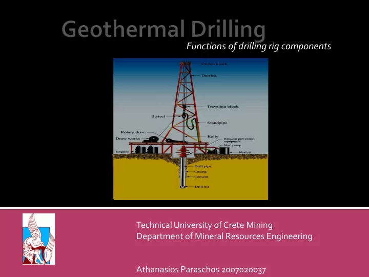
Functions of drilling rig components
Technical University of Crete Mining Department of Mineral Resources Engineering Athanasios Paraschos 2007020037
SLIDE 2
Drilling rigs create boreholes on that are used
in natural gas extraction
A rig that can drill a 10,000ft (3km) well
requires 50-75 people, 35-45 semi tracks to move and assemble it.
Drilling operations continue 24hrs and 7days
for almost full year
SLIDE 3
By power: mechanical, electrical, hydraulic,
steam and so on
By pipe used: cable, metallic or plastic drill, coil
tubing
By height: single, double, triple By rotation type: rotary table, top drive, sonic.. By position of derrick: vertical, slant
SLIDE 4 Source http://www.conservation.ca.gov/dog/picture_a_well/Pages/qh_drill_rig.aspx
SLIDE 5 An assembly of
sheaves or pulleys mounted on beams
The drilling line is
run over it down and threaded
Source http://www.glossary.oilfield.slb.com/DisplayImage.cfm?ID =310
SLIDE 6 An
assembly
sheaves or pulleys
The combination of
travelling block with crown block and drill line lifts weight
Source http://www.rigmanufacturer.com/travelling- block.html
Hook
SLIDE 7 It
is a four legged load carrying structure
It is the most critical structure
as it determines the rig´s depth limit
It carries the load of the
crown block and travelling block
It
should de designed properly to carry largest dry weights
these loads
Source http://www.glossary.oilfield.slb.com/DisplayImage.cfm?ID =310
SLIDE 8 Suspends the weight of the
drilling pipe
It is part of fluid circulation
system and allows for the flow of drilling mud from the standpipe without leaking
It allows the part below it to
rotate
Source http://petroequip.placecat.net/product-1127116-- power_swivel_used_in_drilling_rigs.html
Travelling block Derrick Swivel
SLIDE 9
Is a part
the circulation systems that affects the success
Standing pipe: allows the drilling mud to travel up the derrick and connect to swivel
Drilling mud is pumped from mud tanks by mud pump up the standpipe
Source http://en.wikipedia.org/wiki/File:Oil_Rig_NT8.jpg
Travelling block Derrick Swivel Standing pipe Mud pump Mud tank
SLIDE 10 Is used to turn the drilling
pipe
It is a special section of pipe
that is attached to the bottom
the swivel by threading.
Drilling pipe rotates as the
rotary table turns. The kelly connects these structures to the swivel
Source http://en.wikipedia.org/wiki/File:Oil_Rig_NT8.jpg
Kelly fitted into drive bushing
SLIDE 11
A powered gear located inside the rotary table turns the master bushing.
The master bushing turns the Kelly bushing.
The square or hexagonal opening in the Kelly Bushing fits against the flat sides of the Kelly itself and causes it to spin.
The Kelly slides up and down freely inside the opening in the Kelly Bushing allowing it to move down as the bit drills into the hole
The drill stem and bit are turned by the Kelly.
Source http://en.wikipedia.org/wiki/File:Oil_Rig_NT8.jpg
SLIDE 12 It is used in both the Kelly
system andTop Drive system.
The rotary table is located on
the floor of the rig and it is capable of producing a strong rotating force called
Additional
equipment transmits torque from the rotary table to the drill bit.
Source http://www.shutterstock.com/
SLIDE 13
http://www.youtube.com/watch?v=K9x4atwaCvs
SLIDE 14
Drill Pipe forms the upper part of the drill string.
Each section of pipe is called a joint with a box (female) and pin (male) located on the ends.
Drill pipe is threaded together or assembled in sections and put into the hole as the bit turns.
Drill pipe is hollow and allows fluid
transmitting wires to pass through
SLIDE 15
- It is Located at the bottom end of the drill string and
make contact with the subsurface layers, and drilling through them.
- http://www.nov.com/Downhole/Drill_Bits.aspx
SLIDE 16
http://www.youtube.com/watch?v=fl8L4qSqSqE&feature=related
SLIDE 17
The assembly
preventers, spools, valves, and nipples connected to the top of the wellhead
prevent the uncontrolled escape of steam or water during drilling operations.
http://www.mediafire.com/?uuay2bclaicd2nr taringa.net
SLIDE 18
Mud pump: A large, high-pressure reciprocating pump used to circulate the mud on a drilling rig.
Pressure is as high as 52MPa
Mud pit: Originally, an open pit dug in the ground to hold drilling mud or waste materials such as well bore cuttings
mud sediments.
Steel tanks are much more commonly used for these purposes now, but they are still usually referred to as pits.
http://www.mediafire.com/?uuay2bclaicd2nr taringa.net
SLIDE 19 It is made of heavy steel
pipe
lines the walls of the hole
to prevent the wall of the hole from caving in
prevents
movement
fluids from one formation to another, and to aid in well control.
The space between the
wall of the hole and the casing is filled by cement
SLIDE 20
Friction caused by the drilling operation will tend to
reduce the outside diameter of the drill bit.
Air must be delivered to the piston at sufficient
pressure to activate the reciprocating action, and in turn drive the head into the rock with sufficient strength to fracture and pulverise it
New non-contact effective drilling technologies: are
based on the utilization of water jet, chemical plasma, hydrothermal spallation or laser
SLIDE 21
very promising in deep drilling applications produce boreholes with large constant
diameter without frequent replacement of the drill bits
It would decrease time and money
consumption
It is in research phase
SLIDE 22
Paul K. Ngugi, Geothermal well drilling, Short Course III on Exploration for Geothermal Resources, organized by UNU-GTP and KenGen, at Lake Naivasha, Kenya, October 24 - November 17, 2008
Eustace Githaiga Ndirangu, 2000, selection of a future geothermal drilling rig,geothermal trainng program, the united nations university
Www.wikipedia.org
http://en.wikipedia.org/wiki/Plasma_deep_drilling_technology#High- energetic_electrical_plasma
http://www.geothermalanywhere.com/en/news/98-the-official-opening- research-center-for-deep-drilling-technologies.html