
SLIDE 1
Blue Whale Blue Whale 250 250 Blue Whale Blue Whale 250 250
FOUR STROKE FOUR STROKE
1
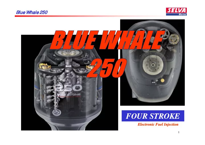
FOUR STROKE FOUR STROKE Electronic Fuel Injection Electronic Fuel - - PowerPoint PPT Presentation
Blue Whale Blue Whale 250 Blue Whale Blue Whale 250 250 250 FOUR STROKE FOUR STROKE Electronic Fuel Injection Electronic Fuel Injection 1 Blue Whale Blue Whale 250 Blue Whale Blue Whale 250 250 250 Content Concept Concept
1
2
3
DOHC 16valve DOHC 16valve DOHC 24valve DOHC 16valve 4 DOHC 16valve DOHC 16valve Variable valve control DOHC 16valve
5
ECU for US & EU are different (emission) Difference points Difference points compared to F225 6
7
Blue Whale 250 EFI 550-1000rpm 8 278kg
Timing belt layout Knock sensor Variable camshaft timing I njector location Canister system Single throttle body Electric throttle actuator I gnition coil with plug cap I njector location Electric throttle actuator Less fuel return to VST Large intake silencer to VST Large intake manifold Big surge tank
9
10
11
ECU
EUR---6P2-00 12
US/ CAN/ JPN ---6P2-20
13
14 No return from fuel rails to VST (similar to F150)
69J Out Put at WOT 46amps Charging at WOT 27amps
15
Sensor number= 7 pcs SW number= 2 pcs
@ EX cam position sensor use to check the piston position of TDC (compression or exhaust) because the injection control is sequential. On starting group injection is used for quick starting. If you don’t use group injection you have to crank 3 rotations (only one EX cam position sensor) in order to determine which cylinder to inject
16
have to crank 3 rotations (only one EX cam position sensor) in order to determine which cylinder to inject. @ IN cam position sensor is used to check and feed back the V .C.T. action to the ECU.
Two TPS sensor installed into one box Two APS sensor installed into one box.
17
18
19
Fuel Filter Mesh Size:30μ
Fuel Filter Mesh Size:30μ
F250A
25μ 32μ
Electrical fuel feed pump
59μ
20
30μ 30μ
The engine oil using V.C.T. fluid 21
OIL PAN
22
SEA
23
Term :100h or 6 months Term :200h or 1 year Term :1000h or 5 years 24
25 5000rpm
Movement by solenoid OCV is constantly regulating y g g the oil pressure in the actuator so that it retards or advances until required camshaft angle is met. 0.2mm mesh Movement by spring T t d f 400h ith t Tested for 400h without changing oil > no problems. Oil change > every 100h 26 Over 2000 RPM every 0,2s a measurement takes place, recalculating the timing
27
A.P .S.(Accelerator Position Sensor) E.T.V . (Electronic Throttle Valve) ECM Mechanical cable Electrical wire C d t l t Electrical wire C d t t t @If the electronic throttle system fails, the engine rpm is automatically limited to 1400rpm. @Key SW ON: The E.T.V . motor receives electric power and starting preparation begins. Command to accelerate Command to accelerate Command to operate motor @Key SW ON: The E.T.V . motor receives electric power and starting preparation begins. ( The throttle valve will move to a closing position.) @During operation:The E.T.V . receives an order from the A.P .S., then the throttle valve moves to open/close. @Key SW OFF:The throttle valve will move to a fully open position first and then fully closed. By doing this the engine learns the fully open and closed positions. If during this SW OFF procedure the engine is SW ON again, this learning action is stopped stopped.
28
Valve opening angle feed back Valve opening angle feed back
Watch each voltage Voltage gap around 2.0v
Crank position sensor I ntake Air pressure sensor
Order a ou d
Signal Signal Movement
5V
Movement Movement From ECM 12V From ECM 12V 29
From ECM From Battery Back-up power supply
0v/ 12v 0v/ 12v 30
The ECM controls the OCV by supplying 12v power for a certain time.
Pull the throttle cable towards the engine to remove any free play in the cable before adjusting the position of the throttle cable joint. Check the mark “b” on the lever “4” has passed the mark “c” on the stopper “5” when the remote control lever is in the fully open position. If the pp y p p adjustment procedure is out of specification the throttle valve may not fully close when throttle lever is fully reduced.
31
When new belt is installed : Turn the flywheel and align all marks and belt lines (A/B1/B2/B3/B4). When belt is re-used : Turn the flywheel and align all marks
32
y g (A/B1/B2/B3/B4) and draw the marks on the belt before removing it.
33
34
Do not turn the crankshaft counterclockwise more than 60 deg. Otherwise the piston and valves will collide with each other and be damaged collide with each other and be damaged.
35
Do not hold the driven sprocket when removing the V.C.T. bolt. Otherwise the V.C.T. assy can be damaged assy can be damaged.
36
I f there is a scratch of more than 0.2mm deep or more than 0.5mm wide on the edge
l if h d t h d replace if rough, damage, or scratched.
37
Components Criterion I G Control I NJ Control V.C.T. Control E.T.V. Control Engine Condition EX Cam position Sensor
Signal error Controlled by crank position sensor and shift to group IG and fix to BTDC10 Controlled by crank position sensor and shift to group INJ Fixed to fully retard position Slightly open Start:Normal Idling:900rpm WOT running:Not possible g
I N Cam position Sensor
Normal Control Normal Control Start:Normal Idling:900rpm WOT running:Possible
T.P.S. (Throttle Position Sensor)
Output voltage is detected below 0.35v or above 4.8v or difference
Controlled by intake air pressure Controlled by intake air pressure Fixed fully retard position 1 TPS: Calculate the voltage B th TPS 1 TPS: Start:Normal Idling:900rpm and not stable WOT i N t ibl p sensor is above 2.3v Both TPS: Kept specific angle WOT running:Not possible (max 4000rpm) Both TPS Start:Normal Idling:900rpm and not stable WOT running:Not Possible (max 1200-1300rpm)
38
Components Criterion I G Control I NJ Control V.C.T. Control E.T.V. Control Engine Condition A.P.S. (Accelerator Position Sensor)
Output voltage is detected blow 0.29v or above 4.8v Normal Control Normal Control Normal Control 1 APS: Calculate the voltage 1 APS: Start:Normal Idling:Normal and stable WOT running:Not possible Both APS: Kept specific angle (max 4000rpm) Both APS: Start:Normal Idling:900rpm and not Idling:900rpm and not stable WOT running:Not possible
I ntake Air Pressure Sensor
Output voltage is detected below 0.2v or above 4.5v Controlled by throttle position sensor Controlled by throttle position sensor Normal Control Slightly open Start:Normal Idling:900rpm and stable WOT running:Possible
39
Engine Condition E.T.V. Control V.C.T. Control I NJ Control I G Control Criterion Components
Slightly open Start:Normal Fixed fully retard Starting: Starting: Output voltage is
Engine
Slightly open Start:Normal Idling:900rpm and stable WOT running:Possible Fixed fully retard position Starting: Controlled by intake air temp Running: Controlled as Starting: Controlled by intake air temp Running: Controlled as Output voltage is detected below 0.18v or above 4.9v
Engine Temperature Sensor
Slightly open Start:Normal Idling:900rpm and stable Normal Control Controlled as 40deg Controlled as 40deg Output voltage is detected below 0.1v or above
I ntake Air Temperature sensor
Controlled as 40deg Controlled as 40deg Slightly open WOT running:Possible 4.6v Start:Normal Idling:900rpm and Normal Control Normal Control Normal Control but retard control Output voltage is detected below
Knock Sensor
Idling:900rpm and stable WOT running:Not possible retard control detected below 0.9v or above 4.0v
If the knock sensor is working during operation, the control map will change to RON 85 map. (Normal control map is RON 94 map) When knocking disappears, the control map will return to normal control when the throttle lever is
possible.
40
Components Criterion I G Control I NJ Control V.C.T. Control E.T.V. Control Engine Condition Overheat SW
SW is ON when engine temperature is below 40 deg or OFF when above 120 deg. Normal Control Normal Control Normal Control Slightly open Start:Normal Idling:900rpm and stable WOT running:Possible
Oil Pressure Sensor
Output voltage is detected below 0.3v or above 4.8v for 260 sec,
engine is stopped. Normal Control Normal Control Normal Control Slightly open Start:Normal Idling:900rpm and stable WOT running:Possible engine is stopped.
Shift-Cut SW
Output voltage is detected below 4.5v or SW is on hen sta ting Normal Control Normal Control Normal Control Slightly open Start:Normal Idling:900rpml and SW is on when starting
neutral SW are on for 5 sec. stable WOT running:Possible
41
Components Criterion I G Control I NJ Control V.C.T. Control E.T.V. Control Engine Condition Oil Control Valve(V.C.T.)
Drive circuit is short or open. Normal Control Normal Control Fixed fully retard position Slightly open Start:Normal Idling:900rpm and stable WOT running:Possible
Crank Position sensor
EX cam position sensor gives signal and crank position sensor gives no signal. Controlled by EX cam position sensor and fixed at BTDC10 Controlled by EX cam position sensor Fixed fully retard position Slightly open Start:Normal Idling:900rpm and stable WOT running:Not ibl signal. possible
E.T.V (Electronic Throttle Valve)
Drive motor is abnormal condition Controlled by A.P.S. Normal Control Fixed to fully retard position Kept specific angle Start:Normal Idling:Not stable WOT running:Not
)
WOT running:Not possible (max 1200-1300rpm)
42
43
INJECTION CONTROL IGNITION CONTROL ENGINE RPM #6 #5 #4 #3 #2 #6 #5 #4 #3 #2 #1 1000 1101 Below 999 #1 1102-1198 1199-1300 1000-1101 1301-1397 1398-1499 Above 1500 =Ignition Standard spark plug: Noise suppression plug g =Injection Standard spark plug: Noise suppression plug I f another type of spark plug is used, the electric throttle system may get ignition noise and engine rpm will drop with + / - 1000rpm.
44
INJECTION CONTROL IGNITION CONTROL ENGINE RPM #6 #5 #4 #3 #2 #6 #5 #4 #3 #2 #1 6200 62 0 Below 6199 #1 6251-6300 6301-6352 6200-6250 6353-6398 6399-6449 =Ignition Above 6450 g =Injection
45
272kPa
46
47
Th ifi d ti di Fuel Feed Pump 5 d Fuel INJ Pump All i j t t b f K it h Injector Engine Condition Always operating The specified time according to the engine temperature Always operating 5 seconds Normal control Running All injectors operate before electric fuel pump operates. Key switch on
Operating 10 seconds and Stop stop 20 seconds till 1200rpm. Stop 1 second (Stop control Key switch off (Engine time lag) stop)
Fuel pump starts operating after receiving pulser signal. After the main key switch is turned on,all injectors are driven to prevent from sticking before the fuel injection pump is driven.
48
# 4
49
50
Point
I f the fuse blows during operation the engine rpm will stay around 1300 rpm. After throttle lever is changed back to neutral the engine rpm will be reduced to around 600 rpm. g g p p
51
52
Target WOT rpm is 5750rpm. (MAX power zone) 53
54
55
56