
SLIDE 1
Fatigue Example
Andrew Ning December 5, 2016
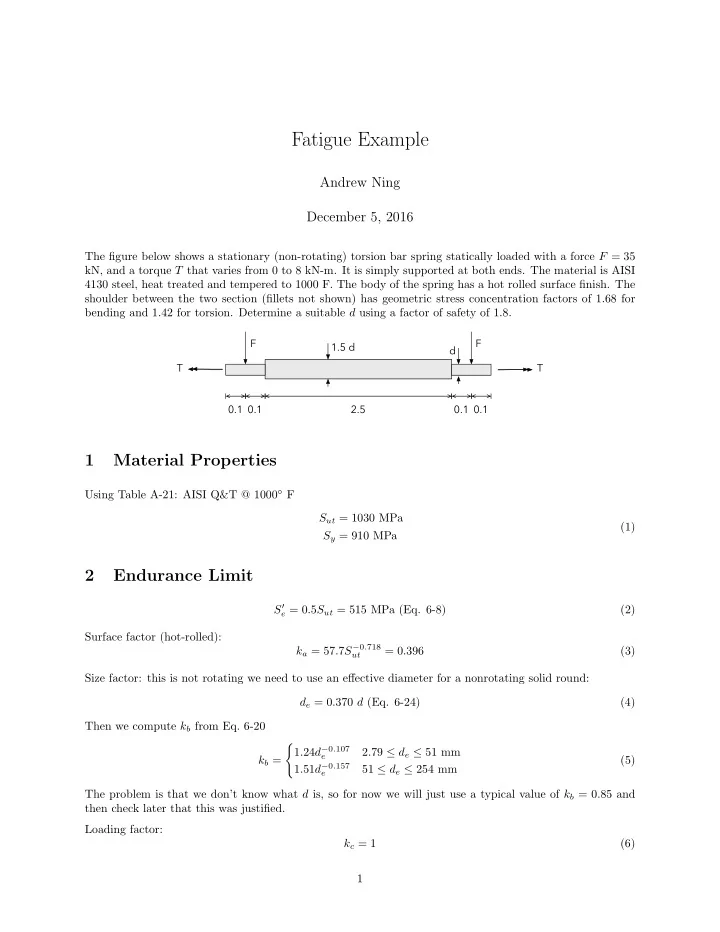
The figure below shows a stationary (non-rotating) torsion bar spring statically loaded with a force F = 35 kN, and a torque T that varies from 0 to 8 kN-m. It is simply supported at both ends. The material is AISI 4130 steel, heat treated and tempered to 1000 F. The body of the spring has a hot rolled surface finish. The shoulder between the two section (fillets not shown) has geometric stress concentration factors of 1.68 for bending and 1.42 for torsion. Determine a suitable d using a factor of safety of 1.8.
F F T T 0.1 2.5 0.1 0.1 0.1 1.5 d d
1 Material Properties
Using Table A-21: AISI Q&T @ 1000◦ F Sut = 1030 MPa Sy = 910 MPa (1)
2 Endurance Limit
S′
e = 0.5Sut = 515 MPa (Eq. 6-8)
(2) Surface factor (hot-rolled): ka = 57.7S−0.718
ut
= 0.396 (3) Size factor: this is not rotating we need to use an effective diameter for a nonrotating solid round: de = 0.370 d (Eq. 6-24) (4) Then we compute kb from Eq. 6-20 kb =
- 1.24d−0.107
e
2.79 ≤ de ≤ 51 mm 1.51d−0.157
e