
SLIDE 1
DSWMA SOUTH LANDFILL FINAL COVER CONSTRUCTION Engineering and - - PowerPoint PPT Presentation
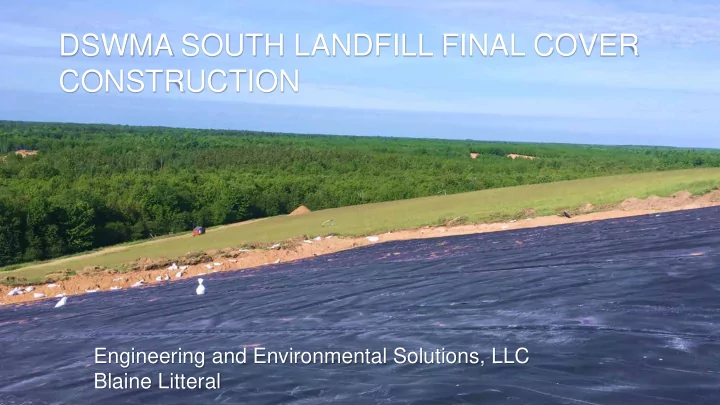
DSWMA SOUTH LANDFILL FINAL COVER CONSTRUCTION Engineering and Environmental Solutions, LLC Blaine Litteral CLOSURE OVERVIEW Final cover was completed in three phases. Phase I of closure was completed in 1997 & 1998 closed 6.59 acres.
E & E Solutions, LLC
E & E Solutions, LLC
E & E Solutions, LLC
E & E Solutions, LLC
E & E Solutions, LLC
E & E Solutions, LLC
E & E Solutions, LLC
E & E Solutions, LLC
Leakage around leachate pump station and poor drainage combined with flaws in primary to secondary welds at site perimeter.
E & E Solutions, LLC
E & E Solutions, LLC
E & E Solutions, LLC
Leakage around leachate pump station was addressed by sealing apparent openings, installing a rain flap to direct storm water away from the building liner connection and providing additional drainage.
E & E Solutions, LLC
E & E Solutions, LLC
E & E Solutions, LLC
E & E Solutions, LLC
E & E Solutions, LLC
Blaine Litteral - 616.566.4609 blaine.litteral@goeeesolutions.com Engineering & Environmental Solutions, LLC www.goEESolutions.com