Development of a global model for BF 3 discharge Van Duy Cung, - - PDF document

development of a global model for bf 3 discharge
SMART_READER_LITE
LIVE PREVIEW

Development of a global model for BF 3 discharge Van Duy Cung, - - PDF document

Transactions of the Korean Nuclear Society Virtual Spring Meeting July 9-10, 2020 Development of a global model for BF 3 discharge Van Duy Cung, Kyoung-Jae Chung*, Y. S. Hwang Department of Energy Systems Engineering, Seoul National University, 1


slide-1
SLIDE 1

Development of a global model for BF3 discharge

Van Duy Cung, Kyoung-Jae Chung*, Y. S. Hwang Department of Energy Systems Engineering, Seoul National University, 1 Gwanak-ro, Gwanak-gu, Seoul, Korea *Corresponding author: jkjlsh1@snu.ac.kr

  • 1. Introduction

Plasma processing has an important role in the electronics industry such as anisotropic etching in the fabrication of micro-electric chips, implantation of many dopants in semiconductors [1]. In the ion implantation technique using boron trifluoride (BF3) gas, the characterization of ion species in the plasma source is of great importance. In this work, we have developed a simplified global model for unmagnetized, low-pressure BF3 plasma. In the particle balance equation, we consider 5 neutral species (B, F, BF, BF2, BF3) and 6 ion species (B+, B++, F+, BF+, BF2+, BF3+). Not only the primary reactions such as the direct ionization, dissociation, and dissociative ionization but also the surface reactions such as dissociative recombination of BF3+, BF2+, and BF+ ions are included in the model. In this paper, the details

  • f the global model and preliminary results are presented.
  • 2. Model

In the present model, we consider the ion species ratio without the magnetic field effect and the power balance equations, compared to the Patel’s model [1]. We only apply the particle balance equations for ion and neutral species, along with the conservation of charge and atomic number. For the primary reactions, we consider the direct ionization, dissociation, and dissociative ionization. The surface reactions include the dissociative recombination of BF3+, BF2+, and BF+ ions. Negative ions and metastables are not considered. Compared to the Patel’s model [1], the excitation reactions (including vibrational excitation processes), momentum transfer reactions and charge transfer reactions are not included in the present model. In this present model, we do not consider two step ionization for any of the species, which is similar to Patel’s assumption [1]. The present global model is developed based on the models provided by Patel [1], Choe [2] and Fukumasa et al [7]. As an initial trial, a cylindrical chamber with a radius of 1 cm and a length of 10 cm is considered. The assumptions used in the present model is well described elsewhere [1]. From the species and the processes which are expressed above, all of the reactions (primary reactions and surface reactions) of the global model are given in Tables I and II.

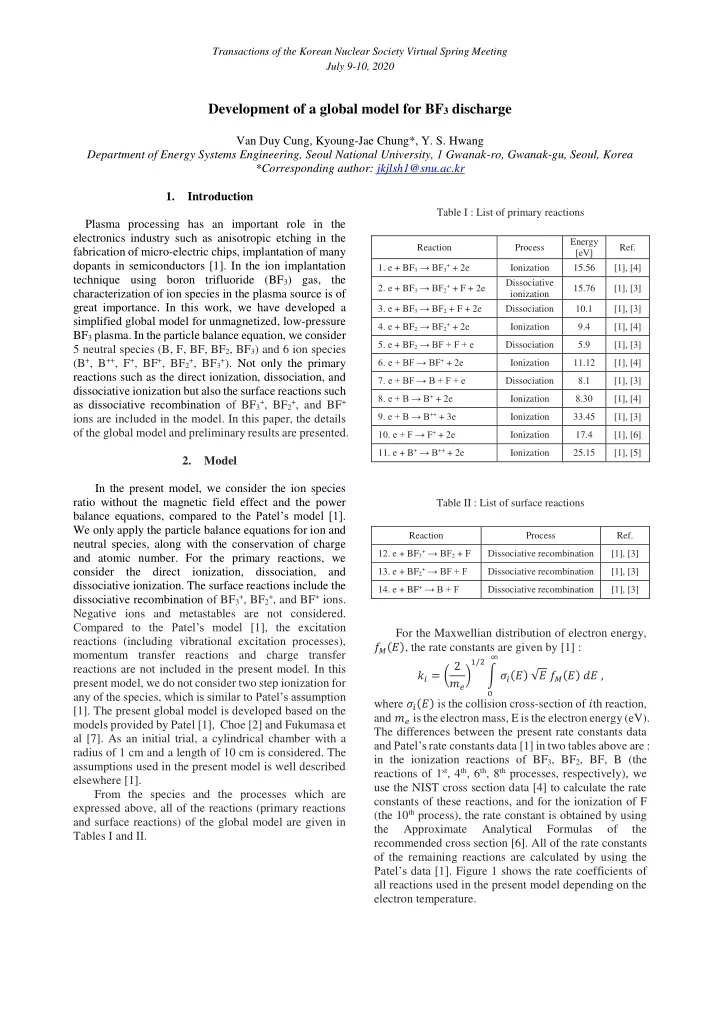
Table I : List of primary reactions Table II : List of surface reactions

For the Maxwellian distribution of electron energy, 𝑔

𝑁(𝐹), the rate constants are given by [1] :

𝑙𝑗 = ( 2 𝑛𝑓 )

1/2

∫ 𝜏𝑗(𝐹) √𝐹 𝑔

𝑁(𝐹) 𝑒𝐹 ∞

, where 𝜏𝑗(𝐹) is the collision cross-section of 𝑗th reaction, and 𝑛𝑓 is the electron mass, E is the electron energy (eV). The differences between the present rate constants data and Patel’s rate constants data [1] in two tables above are : in the ionization reactions of BF3, BF2, BF, B (the reactions of 1st, 4th, 6th, 8th processes, respectively), we use the NIST cross section data [4] to calculate the rate constants of these reactions, and for the ionization of F (the 10th process), the rate constant is obtained by using the Approximate Analytical Formulas

  • f

the recommended cross section [6]. All of the rate constants

  • f the remaining reactions are calculated by using the

Patel’s data [1]. Figure 1 shows the rate coefficients of all reactions used in the present model depending on the electron temperature.

Reaction Process Energy [eV] Ref.

  • 1. e + BF3 → BF3+ + 2e

Ionization 15.56 [1], [4]

  • 2. e + BF3 → BF2+ + F + 2e

Dissociative ionization 15.76 [1], [3]

  • 3. e + BF3 → BF2 + F + 2e

Dissociation 10.1 [1], [3]

  • 4. e + BF2 → BF2+ + 2e

Ionization 9.4 [1], [4]

  • 5. e + BF2 → BF + F + e

Dissociation 5.9 [1], [3]

  • 6. e + BF → BF+ + 2e

Ionization 11.12 [1], [4]

  • 7. e + BF → B + F + e

Dissociation 8.1 [1], [3]

  • 8. e + B → B+ + 2e

Ionization 8.30 [1], [4]

  • 9. e + B → B++ + 3e

Ionization 33.45 [1], [3]

  • 10. e + F → F+ + 2e

Ionization 17.4 [1], [6]

  • 11. e + B+ → B++ + 2e

Ionization 25.15 [1], [5] Reaction Process Ref.

  • 12. e + BF3+ → BF2 + F

Dissociative recombination [1], [3]

  • 13. e + BF2+ → BF + F

Dissociative recombination [1], [3]

  • 14. e + BF+ → B + F

Dissociative recombination [1], [3]

Transactions of the Korean Nuclear Society Virtual Spring Meeting July 9-10, 2020

slide-2
SLIDE 2

1 10 100

  • 30
  • 25
  • 20
  • 15
  • 10

Log10 k (m

3/s)

Electron temperature (eV) Log10 k01 Log10 k02 Log10 k03 Log10 k04 Log10 k05 Log10 k06 Log10 k07 Log10 k08 Log10 k09 Log10 k10 Log10 k11 Log10 k12 Log10 k13 Log10 k14 RATE CONSTANTS OF BF3 PLASMA DISCHARGE (PRESENT)

  • Fig. 1. Rate coefficients of reactions used in the present

model.

According to the assumptions in the present model, we formulate the particle balance equations for all neutral and ion species as following [1,2,7] : 𝑂3𝑜𝑓𝑙07 + 𝑙14𝑜4𝑜𝑓 − 𝑂

1𝑜𝑓𝑙08 − 𝑂 1𝑜𝑓𝑙09 −

𝛿 𝑂

1 𝑈 1

⁄ = 0 (1) 𝑂5𝑜𝑓𝑙02 + 𝑂5𝑜𝑓𝑙03 + 𝑂4𝑜𝑓𝑙05 + 𝑂3𝑜𝑓𝑙07 + 𝑙14𝑜4𝑜𝑓 + 𝑙13𝑜5𝑜𝑓 + 𝑙12𝑜6𝑜𝑓 − 𝑂2𝑜𝑓𝑙10 − 𝛿 𝑂2 𝑈

2

⁄ = 0 (2) 𝑂4𝑜𝑓𝑙05 + 𝑙13𝑜5𝑜𝑓 − 𝑂3𝑜𝑓𝑙06 − 𝑂3𝑜𝑓𝑙07 − 𝛿 𝑂3 𝑈

3

⁄ = 0 (3) 𝑂5𝑜𝑓𝑙03 + 𝑙12𝑜6𝑜𝑓 − 𝑂4𝑜𝑓𝑙04 − 𝑂4𝑜𝑓𝑙05 − 𝛿 𝑂4 𝑈

4

⁄ = 0 (4) 𝑂

1𝑜𝑓𝑙08 − 𝑜1𝑜𝑓𝑙11 − 𝑜1 𝜐1

⁄ = 0 (5) 𝑂

1𝑜𝑓𝑙09 + 𝑜1𝑜𝑓𝑙11 − 𝑜2 𝜐2

⁄ = 0 (6) 𝑂2𝑜𝑓𝑙10 − 𝑜3 𝜐3 ⁄ = 0 (7) 𝑂3𝑜𝑓𝑙06 − 𝑜4 𝜐4 ⁄ − 𝑙14𝑜4𝑜𝑓 = 0 (8) 𝑂5𝑜𝑓𝑙02 + 𝑂4𝑜𝑓𝑙04 − 𝑜5 𝜐5 ⁄ − 𝑙13𝑜5𝑜𝑓 = 0 (9) 𝑂5𝑜𝑓𝑙01 − 𝑜6 𝜐6 ⁄ − 𝑙12𝑜6𝑜𝑓 = 0 . (10) The charge and particle number conservations are [1,2,7] : 𝑜1 +

1 2 𝑜2 + 𝑜3 + 𝑜4 + 𝑜5 + 𝑜6 = 𝑜𝑓 (11)

𝑂

1 + 𝑜1 + 𝑜2 + 𝑂3 + 𝑜4 + 𝑂4 + 𝑜5 + 𝑂5 + 𝑜6 = 𝑂0 =

𝑞 𝑙𝑈 ⁄ (12) 𝑂2 + 𝑜3 + 𝑂3 + 𝑜4 + 2𝑂4 + 2𝑜5 + 3𝑂5 + 3𝑜6 = 3𝑂0 = 3 𝑞 𝑙𝑈 ⁄ (13) where 𝑂

1, 𝑂2, 𝑂3, 𝑂4, 𝑂5 are the densities of B, F, BF,

BF2, BF3, respectively; 𝑜1, 𝑜2, 𝑜3, 𝑜4, 𝑜5, 𝑜6 are the densities of B+, B++, F+, BF+, BF2+, BF3+, respectively; 𝑈

1,

𝑈

2, 𝑈 3, 𝑈 4 are the transit times of B, F, BF, BF2 across the

chamber, respectively; 𝜐1 , 𝜐2 , 𝜐3 , 𝜐4 , 𝜐5 , 𝜐6 are the containment times of B+, B++, F+, BF+, BF2+, BF3+, respectively; and the containment times of B, F, BF, BF2 would be 𝑈

1/𝛿, 𝑈 2/𝛿, 𝑈 3/𝛿, 𝑈 4/𝛿; γ is the sticking factor

  • f B, F, BF, BF2 at the wall; p is the BF3 gas pressure; 𝑈

is the ion and neutral temperature (= 600 K); 𝑜𝑓 is the electron density; 𝑂0 is the density of BF3 molecules before discharge. In the equations which are expressed above, we consider the ratio of 𝜐1, 𝜐2, 𝜐3, 𝜐4, 𝜐5, 𝜐6 to be the ratio

  • f the square root of the respective ion masses, and also

consider the ratio of 𝑈

1, 𝑈 2, 𝑈 3, 𝑈 4 to be the ratio of the

square root of the respective atomic or molecular masses [2,7]. 𝜐1 and 𝑈

1 are calculated as two unknown variables.

  • 3. Preliminary results

As preliminary results, we calculate the dependence

  • f ion species fractions on plasma density, gas pressure

without considering the relation between pressure and electron temperature. Figure 2 illustrates the ion species fractions when changing the plasma density from 1015 m-

3 to 1019 m-3 at fixed operating pressure p = 20 mTorr, the

recombination coefficient and the electron temperature are set as γ = 0.1 and Te = 3 eV, respectively [2]. We can see that the ion species fraction is greatly influenced by the plasma density. When the plasma density increases, the ion species fractions of B+, F+, BF+, and BF2+ increase, while the ion species fraction of BF3+ decreases significantly, indicating the BF3+ is negligible at very high plasma density regime. The ion species fraction of BF2+ is always higher than that of B+, B++, F+, and BF+.

1E15 1E16 1E17 1E18 1E19 20 40 60 80 100

Ion species fraction (%) Plasma density (m

  • 3)

B

+

B

++

F

+

BF

+

BF2

+

BF3

+

Fixed parameters : p = 20 mTorr,  = 0.1, Te = 3 eV (Present)

  • Fig. 2. The dependence of ion species fractions on plasma

density.

10 20 30 40 50 20 40 60 80 100

Ion species fraction (%) Pressure (mTorr) B

+

B

++

F

+

BF

+

BF2

+

BF3

+

Fixed parameters : ne = 10

17 m

  • 3,  = 0.1, Te = 3 eV (Present)

Transactions of the Korean Nuclear Society Virtual Spring Meeting July 9-10, 2020

slide-3
SLIDE 3
  • Fig. 3. The dependence of ion species fractions on gas

pressure.

Figure 3 shows the ion species fractions when the

  • perating pressure is changed from 7 to 50 mTorr. The

setup parameters are : ne = 1017 m-3, γ = 0.1, Te = 3 eV. We can see that when the gas pressure increases, the ion species fractions of B+, F+, BF+, and BF2+ decrease, while the ion species fraction of BF3+ increases dramatically. The ion species fraction of BF2+ is still higher than that

  • f B+, B++, F+, and BF+ for all gas pressure values.
  • 4. Conclusions and Future work

In this paper, we have developed the global model for BF3 plasma discharge which is widely used in plasma

  • processing. The preliminary results show the great

dependency of ion species fraction on the change of the conditions such as the plasma density (while the setup parameters are operating pressure, recombination coefficient and electron temperature) and the operating pressure (while the setup parameters are plasma density, recombination coefficient and electron temperature). In the future, we will add the power balance equation for determining the plasma parameters self-consistently and consider the effect of the external magnetic field. Acknowledgments This research was supported by the National R&D Program through the National Research Foundation of Korea (NRF) funded by the Ministry of Science, ICT & Future Planning (Nos. 2018M2A2B3A02072240 and 2019M2D1A1080261). REFERENCES

[1] K. Patel, "Volume Averaged Modeling of High-Density Discharges", thesis, U. C. Berkeley, 1998. [2] Kyumin Choe, “Development of Hydrogen Cold Cathode Penning Ion Source in Pulsed Operation with High Monoatomic Fraction”, 2018. [3] M. A. Lieberman, A. J. Lichtenberg, “Principles of Plasma Discharges and Materials Processing”, Wiley Interscience, New York, 2005. [4] URL for NIST website : https://www.nist.gov/pml/electron-impact-cross-sections- ionization-and-excitation-database, 2004. [5] K. L. Bell, H. B. Gilbody, J. G. Hughes, A. E. Kingston, and F. J. Smith, J. Phys. Chem. Ref. Data 12, 891, 1983. [6] M. A. Lennon, K. L. Bell, H. B. Gilbody, J. G. Hughes, A.

  • E. Kingston, M. J. Murray, F. J. Smith, J. Phys. Chem. Ref.

Data 17, 1285-1363, 1988. [7] O. Fukumasa, R. Itatani, S. Saeki, J. Phys. D : Appl. Phys. 18, 2433-2449, 1985. Transactions of the Korean Nuclear Society Virtual Spring Meeting July 9-10, 2020