
SLIDE 1
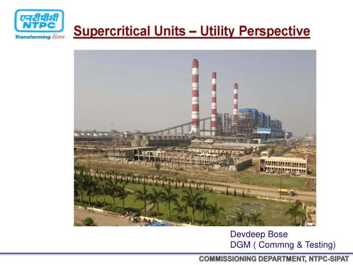
Devdeep Bose DGM ( Commng & Testing)
Devdeep Bose DGM ( Commng & Testing) INTRODUCTION TO SUPER - - PowerPoint PPT Presentation
Devdeep Bose DGM ( Commng & Testing) INTRODUCTION TO SUPER CRITICAL UNI - POINTS OF DISCUSSION SUB CRITICAL & SUPER CRITICAL BOILER SIPAT BOILER DESIGN SIPAT TURBINE DESIGN DESIGN PARAMETERS
Devdeep Bose DGM ( Commng & Testing)
POINTS OF DISCUSSION
Description unit 660 500
S/H STEAM FLOW T/HR 2225 1625 SH STEAM PR KG/CM2 256 179 SH STEAM TEMP
0C
540 540 RH STEAM FLOW T/HR 1742 1397.4 RH STEAM TEMP INLET
0C
303.7 338.5 RH STEAM TEMP OUTLET
0C
568 540 RH STEAM PRESS INLET KG/CM2 51.17 46.1 FEED WATER TEMP
0C
291.4 255.2
Description 660 MW 500 MW Structural Steel Erection 7383
9200
Boiler Proper & Accessories (Pre. Parts) 7080
5300
Refractory, Insulation & Cladding 1410
2000
Power Cycle Piping 3032
2200
Soot Blowing System 54
76
Coal Firing System 3573
2000
Draft System 5275
5200
Fuel oil system 62
200
Miscellaneous System 130
280
Electrical & Instrumentation 282
380
TOTAL
Description 660 MW 500 MW Structural Steel Alloy Steel
Carbon Steel
Water wall T22
Carbon Steel
SH Coil T23, T91
T11, T22
RH Coil T91,Super 304 H
T22, T91,T11
LTSH T12
T11
Economizer SA106-C
Carbon Steel
Welding Joints (Pressure Parts) 42,000 Nos
24,000 Nos
Slno 660 MW 500 MW Remarks 1 STRUCTURALS a
Entire structural is bolting type- entire structure is bolted. Holes are drilled on the columns and gusset plates, and supplied with matching plates. Structural is assembled at site with welding Advantages (660MW) of Bolting structure:
b.
No Welding work involved in assembly/ Erection , except Walkway rail post welding Assembly is carried
Can be dismantled if required ( For Maintenance purpose)
c
Material supply is tier wise including staircases, railing, gratings etc. Material is supplied as per the erection sequence. Erection completion tier wise, including gratings, platforms , staircases etc.
1 Cost of SG Package 1970.73 Cr 1020.54 Cr with ESP 2 Cost of ESP 183.54Cr 3 Total cost of Boiler + ESP 2154.27 Cr 1020.54 Cr 4
Cost of Boiler per MW with ESP
5 Cost of TG for entire stage 1204.72 Cr 634.31 Cr 6 TG cost per MW
Description unit
S/H STEAM FLOW T/HR 2225 SH STEAM PR KG/CM2 256 SH STEAM TEMP
0C
540 RH STEAM FLOW T/HR 1742 RH STEAM TEMP INLET
0C
303.7 RH STEAM TEMP OUTLET
0C
568 RH STEAM PRESS INLET KG/CM2 51.17 FEED WATER TEMP
0C
291.4
Quoted Turbine Heat Rate 100% Load 1904 Kcal / KWH 80% Load 1924 Kcal / KWH 60% Load 1973 Kcal / KWH 50% Load 2065 Kcal / KWH Net Plant Heat Rate = NTRH = 2207 KCal / KWHR ( at 100% TMCR) 80% TMCR = 2222 Kcal / KWHR 60% TMCR = 2276 Kcal / KWHR 50% TMCR = 2376 Kcal / KWHR Plant Efficiency at 100% TMCR = 38.96% 80% TMCR = 38.7 % 60% TMCR= 37.78% 50% TMCR = 36.19% = Boiler Efficiency 100% TMCR 86.27% 80% TMCR 86.60% 60% TMCR 86.68% 50% TMCR 86.91%
Supplier : M/s DOOSAN Erection By : M/s L&T
When Water is heated at constant pressure above the critical pressure, its temperature will never be constant No distinction between the Liquid and Gas, the mass density of the two phases remain same No Stage where the water exist as two phases and require separation : No Drum The actual location of the transition from liquid to steam in a once through super critical boiler is free to move with different condition : Sliding Pressure Operation For changing boiler loads and pressure, the process is able to optimize the amount of liquid and gas regions for effective heat transfer. UNDERSTANDING SUPER CRITICAL TECHNOLOGY
SUPER CRITICAL BOILER CYCLE WITH SH, RH & Regeneration
Steam flow :2225 T/Hr Steam temp : 540 ‘c Steam Pres : 256 kg/cm2 RH pre : 51.6 Kg/cm2 RH Temp : 568’c Feed water Temp : 291’c
540’C 568’C ENTROPY TEMP 1 2 3 4 5
HPT IPT LPT
C O N D E N S E R
FEED WATER FRS
S T O R A G E T A N K
SEPARATOR
BWRP MS LINE HRH LINE VERTICAL WW
ECO I/L ECO JUNCTION HDR ECO HGR O/L HDR FUR LOWER HDR
FUR ROOF I/L HDR DIV PANELS SH PLATEN SH FINAL RH FINAL SH LTRH ECONOMISER
290°C, 302 KSC 411°C, 277Ksc 411°C, 275 Ksc 492°C, 260 Ksc 540°C, 255 Ksc 305°C, 49 Ksc 457°C, 49 Ksc 568°C, 47 Ksc
G
LPT
Boiling process in Tubular Geometries
Heat Input Heat Input Water Water Water Steam Steam Partial Steam Generation Complete or Once-through Generation
Advantage Disadvantage over Vertical water wall
employ vertically oriented tubes.
the lower furnace where the burners are located and the heat input is high.
(two passes), the mass flow per tube can be kept high enough to ensure sufficient cooling.
fluid temperature.
the desired flow per tube by wrapping them around the furnace to create the enclosure.
zones to maintain a nearly even fluid temperature at the outlet of the lower portion of the furnace.
enclosure, fabrication and erection are considerably more complicated and costly.
SPIRAL WATER WALL
ADVANTAGE Benefits from averaging of heat absorption variation : Less tube leakages Simplified inlet header arrangement Use of smooth bore tubing No individual tube orifice Reduced Number of evaporator wall tubes & Ensures minimum water flow Minimizes Peak Tube Metal Temperature Minimizes Tube to Tube Metal Temperature difference DISADVANTAGE Complex wind-box opening Complex water wall support system tube leakage identification : a tough task More the water wall pressure drop : increases Boiler Feed Pump Power Adherence of Ash on the shelf of tube fin
FD FAN 2 No’S ( AXIAL ) 11 kv / 1950 KW 228 mmwc 1732 T / Hr PA FAN 2 No’s ( AXIAL) 11 KV / 3920 KW 884 mmwc 947 T / Hr ID FAN 2 No’s ( AXIAL) 11 KV / 5820 KW 3020 T / Hr TOTAL AIR 2535 T / Hr SH OUT LET PRESSURE / TEMPERATURE / FLOW 256 Ksc / 540 C 2225 T / Hr RH OUTLET PRESSURE/ TEMPERATURE / FLOW 46 Ksc / 568 C 1742 T / Hr SEPARATOR OUT LET PRESSURE/ TEMPERATURE 277 Ksc / 412 C ECONOMISER INLET 304 Ksc / 270 C MILL OPERATION 7 / 10 COAL REQUIREMENT 471 T / Hr SH / RH SPRAY 89 / 0.0 T / Hr BOILER EFFICIENCY 87 %
1. High erosion potential for pulverizer and backpass tube is expected due to high ash content.
Index is relatively low but combustion characteristic is good owing to high volatile content.
Parameter Unit Design Coal Worst Coal Best Coal Young Hung #1,2(800MW) Tangjin #5,6(500MW) High Heating Value kcal/kg 3,300 3,000 3,750 6,020 6,080 Total Moisture % 12.0 15.0 11.0 10.0 10.0 Volatile Matter % 21.0 20.0 24.0 23.20 26.53 Fixed Carbon % 24.0 20.0 29.0 52.89 49.26 Proximate Analysis Ash % 43.0 45.0 36.0 13.92 14.21 Fuel Ratio (FC/VM)
1.00 1.21 2.28 1.86 Combustibility Index
2,353 2,476 2,781 3,492 Carbon % 39.53 31.35 40.24 63.03 62.15 Hydrogen % 2.43 2.30 2.68 3.60 3.87 Nitrogen % 0.69 0.60 0.83 1.53 1.29 Oxygen % 6.64 5.35 8.65 7.20 7.80 Sulfur % 0.45 0.40 0.60 0.72 0.68 Ash % 43.00 45.00 36.00 13.92 14.21 Ultimate Analysis Moisture % 12.00 15.00 11.00 10.00 10.00 Grindability HGI 50 47 52 45 48 ASTM Coal Classification
Bituminous Hi–Vol. ‘C’ Bituminous Hi–Vol. ‘C’ Bituminous Midium Vol. Bituminous Hi–Vol. ‘C’ Bituminous
Coal Analysis
1. Lower slagging potential is expected due to low ash fusion temp. and low basic / acid ratio.
potential is expected due to low Na2O and CaO content.
Parameter Unit Design Coal Worst Coal Best Coal Young Hung #1,2(800MW) Tangjin #5,6(500MW) SiO2 % 61.85 62.40 61.20 57.40 57.40 Al2O3 % 27.36 27.31 27.32 29.20 29.20 Fe2O3 % 5.18 4.96 5.40 4.40 4.40 CaO % 1.47 1.42 1.52 2.70 2.70 MgO % 1.00 1.03 0.97 0.90 0.90 Na2O % 0.08 0.08 0.08 0.30 0.30 K2O % 0.63 0.32 1.22 0.70 0.70 TiO2 % 1.84 1.88 1.80 1.30 1.30 P2O5 % 0.54 0.55 0.44
% 0.05 0.05 0.05
Analysis Others %
3.10 Initial Deformation
1150 1100 1250 1200 1200 Softening
1400 1280 1400 Ash Fusion
(Reducing Atmos.) Flow
1400 1280 1400 Ash Content kg/Gcal 130.3 150.0 96.0 23.12 23.37 Basic / Acid B/A 0.09 0.09 0.10 1.63 1.63
Ash Analysis
Constant Pressure Control Above 90% TMCR The MS Pressure remains constant at rated pressure The Load is controlled by throttling the steam flow Below 30% TMCR the MS Pressure remains constant at minimum Pressure Sliding Pressure Control Boiler Operate at Sliding pressure between 30% and 90% TMCR The Steam Pressure And Flow rate is controlled by the load directly BOILER LOAD CONDITION
+1
20 40 60 80 100 Efficiency Change % Boiler Load % Variable Pressure CONSTANT PRESSURE Vs VARIABLE PRESSURE BOILER CHARACTERSTIC
Benefits Of Sliding Pressure Operation ( S.P.O)
Able to maintain constant first stage turbine temperature Reducing the thermal stresses on the component : Low Maintenance & Higher Availability No additional pressure loss between boiler and turbine. low Boiler Pr. at low loads.
WHY NOT S.P.O. IN NATURAL/CONTROL CIRCULATION BOILERS
Circulation Problem : instabilities in circulation system due to steam formation in down comers. Drum Level Control : water surface in drum disturbed. Drum : (most critical thick walled component) under highest thermal stresses
LMZ (LENINGRADSKY METALLICHESKY ZAVOD) K STANDS FOR KLAPAN LTD.,BULGARIA WHICH SUPPLIES TURBINE,NOZZLES,DIAPHRAGMS, SEALS,BLADES ETC.
1.TG DECK IS VIS SUPPORTED AND HAS 26 CONCRETE COLUMNS (T1 – T26). 2.TG HALL IS CONSTITUTED OF 3 MAINS ROWS OF COLUMNS – A,B ,C ROW AND TWO BAYS – AB BAY AND BC BAY. THE WIDTH OF AB BAY IS 36m AND BC BAY IS 12m 3.CONDENSER TUBE BANKS (CW PATH) HAS AN INCLINATION OF 40. 4.THERE ARE TWO MAIN EOT CRANES FOR TG HALL.EACH EOT CRANE IS HAVING A CAPACITY OF 200t FOR MAIN HOIST AND 20t FOR AUXILIARY HOIST. 35.5m IS THE MAXIMUM VERTCAL DISTANCE A HOIST CAN TRAVEL.TANDEM OPERATION OF TWO EOT CRANES ARE ALLOWED.
Ext. No Source Of Extraction Destination Equipments
1 13th stage of HPT HPH-8 2 CRH HPH-7 3 3rd stage of IPT HPH-6 * 3 3rd stage of IPT TDBFP 4 6th stage of IPT DEAERATOR 5 8th stage of IPT LPH-4 6 11th stage of IPT LPH-3 7 2nd stage of LPT LPH-2 8 4th stage of LPT LPH-1
LMZ
64000 m3/hr
77 mm Hg (abs) at 33 0C 89 mm Hg (abs) at 36 0C
1
22.225 (OD)x0.71 (t) - 29920 22.225 (OD)x1.00 (t) - 2080
ASTM A-249 TP 304
3.40C
100C
238.75 Kg/s
32.15 Ksc
395 m
1480 rpm
972.3 KW
6
double entry
7.43 m
769.950 TPH
186.2
0C
14.05 ata
ata
335.78 ata
187.9
0C
22.01 ata
4830 m
6275 rpm
1490 rpm
TPH
6505 rpm
barrel
7
15 TPH
1283.14 TPH
186.2 0C
14.10 ata
28.24 ata
335.83 ata
187.8 0C
29.06 ata
4580 m
4678 rpm
2098 rpm
365 TPH
6505 rpm
barrel
7
20 TPH
324.509 TPH
43 ata
306.7 m
1486 rpm
310.1 KW
5
centrifugal, single entry
1090 mm
: 660MW
: 247KSC
: 5370C
: 2023.75T/HR
: 48KSC
: 298.710C
: 43.2KSC
: 5650C
: 1681.12T/HR.
: 0.105KSC (abs.)
: 64000M3/HR
: 286.350C
: 47.5 – 51.5 Hz
3000 rpm
Electrosila
8
36.362 m
HPT 17 IPT 11x2 LPT-1 5x2 LPT-2 5x2 Total 59
Mode of Governing Nozzle Type E/H Control fluid Firequel-L make Supresta-USA Normal Operating Pr. 50 Ksc Capacity 600 lpm Fluid pump motor rating 200 KW Filter material Ultipor Mesh size 25 µ
Turbine protection system consists of Two Independent channels, each operating the corresponding solenoid (220V DC) to trip the Turbine in case of actuation of remote protection Hydraulic Protection: Apart from the Electrical Trip, Turbine is equipped with the following Hydraulic Protections:
Contd..
5.Axial shift Very High (2V3) [-1.7mm, +1.2mm] 6.Turbine bearing vibration : Very High (2V10 including X & Y directions)* >11.2mm/sec (Td=2 sec) 7.Lube oil tank level very Low (2V3)* Td=3sec (Arming with two stop valves open) 8.Lub oil pressure Very Low (2V3) < 0.3 Ksc; Td =3 sec (Arming with two stop valves open) 9.Condenser pressure Very High (2V3) > - 0.7ksc (Arming with condenser press < 0.15 ksc Abs) Contd
10.M.S. temp Very Low (2V3) < 470 deg C (arming > 512 deg C)* 11.M.S. temp Very High (2V3) > 565 deg C* 12.HRH temp Very Low (2V3) < 500deg C (arming > 535 deg C)* 13.HRH temp Very High (2V3) > 593deg C* 14.HPT outlet temperature Very High (2V4) > 420 deg C Contd…
15.Gen seal oil level of any seal oil tank Very Low (2V3)* < 0 mm;Td=15 sec (Arming with any two stop valves open) 16.All Generator seal oil pumps OFF (3V3)* Td: 9 sec (Arming with any two stop valves open) 17.Generator Stator winding flow Very Low (2v3) < 17.3 m3/hr; Td =120 sec (Arming with any two stop valves open) 18.Generator hot gas coolers flow Very LOW (2V3)* : <180m3/hr; Td=300sec(Arming with any two stop valves open) 19.Generator cooler hot gas temp. Very High(2V4) > 85 deg (Td = 300sec Contd
20.MFT operated: (2V3) 21.Deareator level Very High (2V3) > 3400 mm* 22.HP heater level protection operated (2V3)* 23.Generator Electrical protection operated (2V3) 25.Turbine over speed protection operated (114%) 26.Turbine Controller failure protection operated (2V3)
1ST UNIT SYNCHRONIZED AT : 18.02.2011 1ST UNIT FULL LOAD ACHIEVED AT : 2nd UNIT SYNCHRONIZED AT : 03.12.2012 2ND UNIT FULL LOAD ACHIEVED AT : 24.12.2012
PRE – COMMISSIONING ACTIVITIES
CHEMICAL CLEANING OF BOILER :
REQUIRED FOR Maintaining steam quality at the turbine inlet. Minimizing corrosion of the metal surface of boiler.
DETERGENT FLUSHING OF PRE-BOILER SYSTEM
To remove dirt ,oil ,grease etc., from Condensate ,Feed water, Drip and Extraction steam lines of HP and LP heaters prior to putting these systems in regular service. This is to ensure flow of clean condensate and feed water to the boiler.
STEAM BLOWING OF POWER CYCLE PIPING :
The purpose of steam line blowing is to remove pipe slag, weld bead deposits and other foreign material from the main and reheat steam systems prior to turbine operation. The cleaning is accomplished by subjecting the piping systems to heating, blowing steam and cooling cycles in sufficient number and duration until clean steam is
SAFETY VALVE FLOATING
PRE – COMMISSIONING CHECKS All commissioning procedure should be finalized. P&I Drawings should be finalized and available with site engineer Different systems check list should be finalized with all concerned agencies All Field quality checks should be completed. P&I Checks should be finalized. Start – Up procedure should be finalized
COMMISSIONING SEQUENCE OF TG SIDE 1.Commissioning of stator water cooling system for HV testing before generator rotor insertion. a) Stator water pump trial run. b) Flushing of the system bypassing winding. c) Flushing of the system through the winding. 2.Commissioning of MCW,ACW and DMCW system. a) Trial run of pumps. b) Flushing of the system. 3.Detergent Flushing of pre boiler system (Feed water ,condensate ,HPH and LPH drip system) a) Cold water flushing until turbidity comes below 5NTU. b) Hot water flushing (600C) with 2 hrs circulation of each circuit. c) Raising water temperature to 600C and addition of Detergent d) (Coronil 100%)
e) Circulation through each circuit for 2 hrs. f) Hot draining of the system g) DM water rinsing of each circuit until conductivity comes below 5µs/cm and oil content BDL. h) Passivation with ammonia and hydrogen peroxide solution at a temperature of 400C. i) Draining of the system.
5.Trial run of MDBFP. 6.Lube oil and seal oil flushing of main TG. 7.CF system flushing. 8.Condenser flood test. 9.Trial run of CEPs 10.Commissioning of generator gas system. 11.Generator ATT. 12.Calibration of HPCVs and IPCVs 13.Putting turbine on barring. 14.Vacuum pumps trial run.
15.Commissioning of seal steam system. 16.Commissioning of HP and LPBP system.
18.Lube oil flushing of TDBFP. 19.Steam blowing of TDBFP steam line. 20.Commissioning of TDBFP.
FUR DRAFT SYSTEM SEC AIR SYSTEM TG ON BARRING BRP TRIAL RUN TG LUBE OIL / GEN SEAL OIL SYSTEM FURNACE READINESS FUEL OIL SYSTEM READINESS DDCMIS FSSS READINESS MFT CHECKING GATES, DAMPERS / VALVES TG : SG : (13 / 190 ) STATOR COOLING WATER CW SYSTEM READINESS CHEMICAL CLEANING OF BOILER MS Line Welding Completion ( 30 Pen) CRH Line Welding Completion ( 12 Pen) HRH Line Welding Completion (34 Pen) MS Line Hanger Erection Cold Setting CRH Line hangers Cold Setting HRH Line Hangers Cold Setting MS Line Insulation CRH Line Insulation HRH Line Insulation MS Line HT CRH Line HT HRH Line HT COMPRESSED AIR SYSTEM READINESS AUX PRDS READINESS CONDENSER VACCUM SYSTEM
POWER CYCLE PIPING STEAM BLOWING
UNIT SYNCHRONIZTION
MDBFP Trial CEP Trial TG SEAL STEAM SYSTEM TG CONTROL FLUID SYS TG GOV SYSTEM GEN GAS SYSTEM
Questions Please Enlighten Us Discussion
Reduced number of evaporator wall tubes. Ensures minimum water wall flow.
Horizontal and vertical buck stay with tension strip
Horizontal buck stay