
SLIDE 1
D
Technical details subject to change
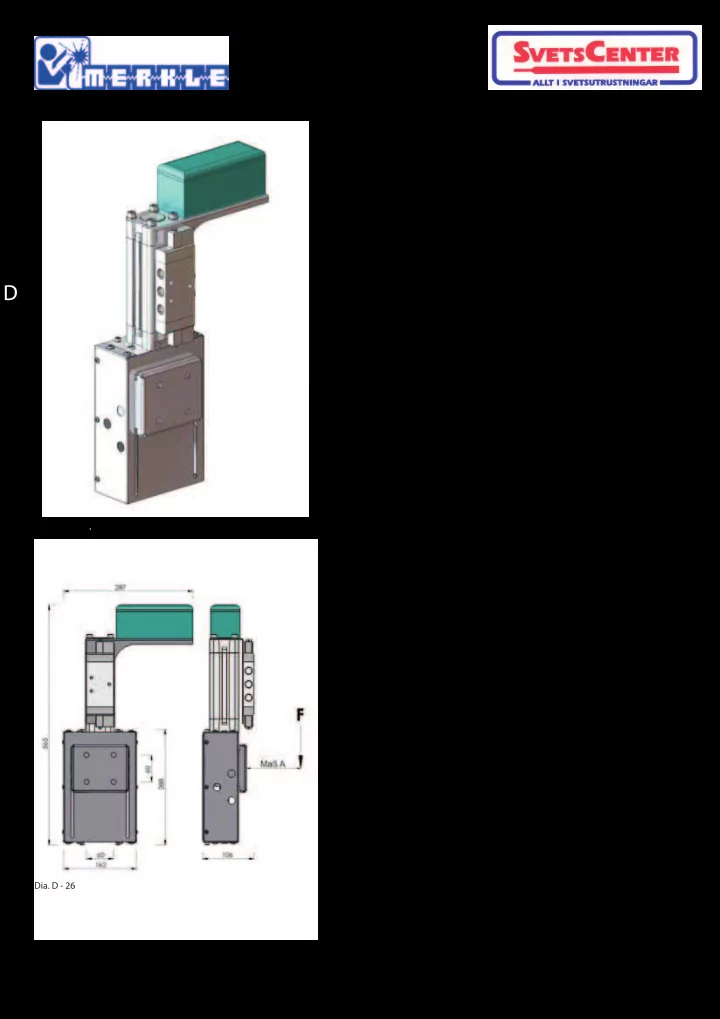
Torch Postioning Systems Pneumatic Stroke Carriage
Technical Details:
Loading F: 300 N
- max. distance A:
250 mm from flange plate Stroke: 100 mm Lifting force: 870 N at 6 bar Weight : 11,2 kg
Pneumatic Stroke Carriage part no. 019.0.1844
The stroke carriage is used for a simple, fast action setting or positioning of the welding torch or jigs. Especially useful when the operating position
- f the jig or torch blocks access to the clamping
device (chucks etc) and prevents a fast change of components to be welded The stroke range is achieved through a double acting pneumatic cylinder. The carriage is fitted with 2 position sensors and maintenance free, light action guides. The stroke range is 100 mm. Delivery including 5/2-direction control valve.
- Dia. D - 25
.
- Dia. D - 26