SLIDE 1 P R E S E N T E D B Y:
I R A B ROT M A N , P E M O F FAT T & N I C H O L
O C T O B E R 2 5 , 2 0 1 2
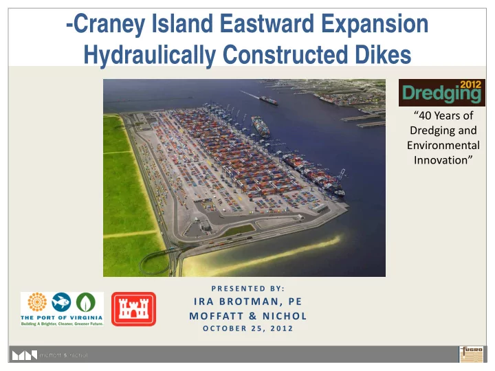
- Craney Island Eastward Expansion
Hydraulically Constructed Dikes
“40 Years of Dredging and Environmental Innovation”
SLIDE 2
Craney Island Eastward Expansion
SLIDE 3 CIEE Layout
I
Existing CIDMMA CIDMMA East Dike CIEE Main Dike CIEE Cross Dike (typ)
SLIDE 4
Subsurface Stratigraphy
SLIDE 5
CIDMMA Dikes (1954)
SLIDE 6
CIDMMA Dikes (1954)
SLIDE 7
CIDMMA Dikes (1954)
SLIDE 8
Cross Dike Objectives
Experiences with CIDMMA (built to +5’) Minimize Mud Waves Minimize Deformation Minimize Instability – Now and Future Minimize Ultimate Sand Volume Predictable Schedule
SLIDE 9
Cross Dike Alternatives
High strength geotextile/geogrid Pre-dredge Deep Soil Mixing Prefabricated Vertical Drains (PVD)
Build dikes in lifts/stages Allow increase in shear strength Achieve by specifying lift thicknesses and hold times
SLIDE 10 Distance in feet (x 1000)
0.50
- 0.45
- 0.40
- 0.35
- 0.30
- 0.25
- 0.20
- 0.15
- 0.10
- 0.05
0.0 0.0 5 0.1 0.1 5 0.2 0.2 5 0.3 0.3 5 0.4 0.4 5
Elevation in feet (MLLW)
20 40 60
Selected Low Cost, Low Risk Cross Dike
- Final target elevation = +18 ft (MLLW)
- 900 ft Wide
- Built in 3 Stages
Upper Norfolk Clay (Qnu)
Pleistocene/Pliocene Sands (Qnl/Tys)
PVDs
Hydraulic Sand Fill Zone of PVDs
Marine PVDs Marine PVDs Land PVDs
SLIDE 11
Construction Sequence
Place Initial Lift Install Marine PVDs
Initiate Strength Gain
Place Second Lift
Allow Additional Strength Gain
Place Third Lift
SLIDE 12
South and Division Cross Dikes
SLIDE 13 Cross Dikes – Stage 1
Hydraulic Sand Fill, Stage 1
SLIDE 14 Cross Dikes Stage 1 – Marine PVDs
PVDs Outer 3rd
PVDs PVDs
SLIDE 15 Cross Dikes Stage 2A – Sand Fill
Hydraulic Sand Fill, Stage 2A
SLIDE 16
Rendering Post Stage 3
SLIDE 17
Rendering Southeast Cell Closed
SLIDE 18 Borrow Source
Atlantic Ocean Channel
CIEE
SLIDE 19
GLDD – Stage 1
SLIDE 20
Sand Placement
SLIDE 21
SLIDE 22
SLIDE 23
SLIDE 24
SLIDE 25
SLIDE 26
GLDD – Stage 1 – Marine PVDs
SLIDE 27
SLIDE 28
SLIDE 29
PVD Installation Record
SLIDE 30
PVD Tip Elevations
SLIDE 31
Multibeam Survey
SLIDE 32
Multibeam Survey
SLIDE 33
Geotechnical Instrumentation
SLIDE 34
Instrumentation Website
SLIDE 35
Settlement
SLIDE 36
Summary
Schedule Challenges
TOY: Turtles
Contractor Innovation
Spillbarge Specialized Barge for PVDs Positioning /Tracking System
Observational Method Success
Measure behavior of foundation during filling Validate Lift placement schedule and hold times PVD installation verification Control project risk
SLIDE 37
Thank You
Special thanks to:
Virginia Port Authority Corps of Engineers, Norfolk District