SLIDE 1
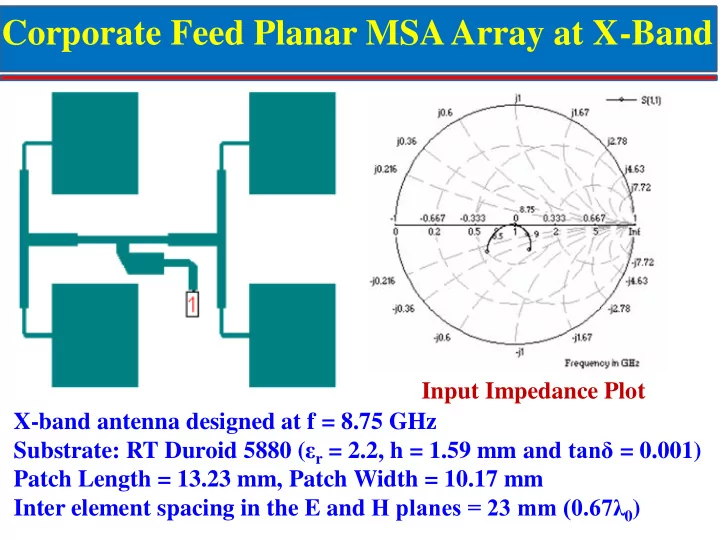
Corporate Feed Planar MSA Array at X-Band
X-band antenna designed at f = 8.75 GHz Substrate: RT Duroid 5880 (εr = 2.2, h = 1.59 mm and tanδ = 0.001) Patch Length = 13.23 mm, Patch Width = 10.17 mm Inter element spacing in the E and H planes = 23 mm (0.67λ0) Input Impedance Plot
SLIDE 2
BW for VSWR ≤ 2 is more than 500 MHz (~6%) Radiation Pattern at 8.75 GHz
Corporate Feed 2x2 MSA Array Results
SLIDE 3
8x8 Corporate feed MSA Array
SLIDE 4
8x8 Corporate feed MSA Array Results
BW for VSWR < 1.5 is 8.55 - 9.0 GHz (~5%) Radiation Pattern at 8.75 GHz E-Plane HPBW = 9.9° H-Plane HPBW = 9.4° Max SLL = –12.5
Max Gain = 21.3 dB
SLIDE 5 Air gap 21 mm
BW is 16% (8.7 -10.2 GHz)
Broadband 4x4 EMCP MSA Array
SLIDE 6 6
BW for VSWR 2 is 13% (8.75 to 10 GHz)
Air gap 240 mm
Isolation between ports:
Sum to Diff. < -20 dB
< -40 dB
Monopulse System using EMCP MSA Array having Series and Corporate Feeds
SLIDE 7 7
- Max. Gain = 24.7 dBi at 9.7GHz
- Variation in Gain < 0.5 dB
- ver the bandwidth of 1 GHz
- HPBW: 9° in Azimuth
and Elevation Planes
Monopulse System using EMCP MSA Array having Series and Corporate Feeds - Results
SLIDE 8 1B7T Space-Fed Array Top View 1B7T Space-Fed Array Side View
r1 r2 x y s Ф x1 r
s h2 h3
Ө
Parasitic Elements h1 Radiating Element Coaxial Feed Ground Plane h
Elements Value (mm) Bottom element radius (r) 13.1 Top element radius (r1, r2) 13.1, 12.7 Inter-element Spacing (s) 33 Air gap (g) 25.85 (λ0/2)
Space Fed CMSA Array (1B7T)
SLIDE 9
1B7T Space-Fed CMSA Array Results
VSWR vs Frequency Plot Gain vs Frequency Plot H-Plane Radiation Pattern E-Plane Radiation Pattern
SLIDE 10 (a) Fabricated 3-element broadband linear series-fed antenna array on finite ground plane of 115 mm x 100 mm. Simulated and measured (b) VSWR and (b) Gain vs. frequency plots Measured VSWR ≤ 2 BW = 5.535 to 5.84 GHz (~5%) Max gain of antenna array =13.4 dBi
(a) (b) (c)
Series-Fed Array of Gap Coupled RMSA
SLIDE 11
Elements Value (mm) Square Element (L1 ) 39.6 Air gap (g1) 3 Feed Offset (s) 2.3 Quarter wave Transformer (l2 x w2) 16 x 9.2
EMCP Dual Polarized MSA in S-Band
SLIDE 12
EMCP Dual Polarized MSA Results
BW for VSWR<2 is from 2.375 to 2.725 GHz (~13%) S21 < -40 dB
SLIDE 13 3x3 Power Divider for Two Ports Microstrip Line Feed Network Top 6x6 Radiating Elements Integrated 6x6 EMCP Antenna Array
EMCP Dual Polarized MSA Array at 5.8 GHz
SLIDE 14 Measured (a) VSWR, (b) S21 and (c) Gain vs. frequency plots
- f 6x6 array of EMCP dual polarized antenna
EMCP Dual Polarized MSA Array at 5.8 GHz - Results
SLIDE 15
Phased Array Antenna
SLIDE 16
Active Phased Array Antennas